The service port is the RS-232 connection data terminal equipment (DTE) that uses a standard 9-pin male "D" shell connector. To connect to a personal computer or terminal, you must have a "null modem" cable. Figure 44, Table 16, and Table 17 show the pin layout designations for this connector.
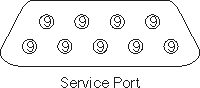
Figure 43. Service port pin layout
|
Table 25. DB-9 RS-232 connector pin assignments
| Pin Number | Signal Name | Abbreviation | Direction Relative to the SAN Data Gateway |
| 1 | Carrier detect | CD | In |
| 2 | Receive data | RD | In |
| 3 | Transmit data | TD | Out |
| 4 | Data terminal ready | DTR | Out |
| 5 | Signal ground | SG | -- |
| 6 | Data set ready | DSR | In |
| 7 | Request to send | RTS | Out |
| 8 | Clear to send | CTS | In |
| 9 | Ring indicator | RI | In |
Table 26. Null modem cable connections
| Service Port Pin Number | Signal Name | 9-Pin AT Connector | 25-pin (DB25) Connector (DTE) |
| 1 | Carrier detect (not used) | N/C (not connected) | N/C (not connected) |
| 2 | Receive data <-> Transmit data | 3 | 2 |
| 3 | Transmit data <-> Receive data | 2 | 3 |
| 4 | Data terminal ready <-> Data set ready | 6 | 6 |
| 5 | Signal ground | 5 | 7 |
| 6 | Data set ready <-> Data terminal ready | 4 | 20 |
| 7 | Request to send <-> Clear to send | 8 | 5 |
| 8 | Clear to send <-> Request to send | 7 | 4 |
| 9 | Ring indicator (not used) | N/C (not connected) |
|