Service Guide
Before you begin to install options in your Models 100 and
200, read the following information:
- Become familiar with the safety and handling guidelines specified under Handling electrostatic discharge-sensitive devices.
- You do not need to switch off the Models 100 and 200 or remove covers to
install or replace hot-swap power supplies or hot-swap hard drives.
- The blue color on components and labels inside your Models 100 and 200
identifies touch points where a component can be gripped, a latch moved, and
so on.
- Ensure that you have an adequate number of properly grounded electrical
outlets for Models 100 and 200 and any other options that you intend to
install.
- Back up all important data before you make changes to hard drives.
- Have a small, flat-blade screwdriver available.
Before you begin installing components, read the safety information
found in Translated safety notices. For translations of the safety notices that are
included in this guide, refer to Safety Information.
To help ensure proper cooling and system reliability, make sure
that:
- Each of the drive bays has either a drive or a filler panel
installed.
- The cover is in place during normal operations, or is removed for no
longer than 30 minutes while the appliance is operating.
| Note: | The front door (Model 100) can be removed permanently without affecting
system reliability.
|
- There is space around the appliance to allow the appliance cooling system
to work properly.
- For the Model 100, leave about 127 mm (5 in.) of space around the
front and rear of the appliance.
- For the Model 200, refer to the documentation that comes with the
rack.
- A removed hot-swap drive is replaced within 2 minutes of removal.
- Cables for optional adapters are routed according to the instructions
provided with the adapters.
- A failed fan is replaced within 48 hours.
Your appliance is designed to operate safely while switched on with the
cover removed. Follow these guidelines when you work inside an
appliance that is switched on:
- Avoid loose-fitting clothing on your forearms. Button long-sleeved
shirts before working inside the appliance; do not wear cuff links while
you are working inside the appliance.
- Do not allow your necktie or scarf to hang inside the appliance.
- Remove jewelry, such as bracelets, rings, necklaces, and loose-fitting
wrist watches.
- Remove items from your shirt pocket (such as pens or pencils) that could
fall into the appliance as you lean over it.
- Take care to avoid dropping any metallic objects, such as paper clips,
hair pins, or screws, into the appliance.
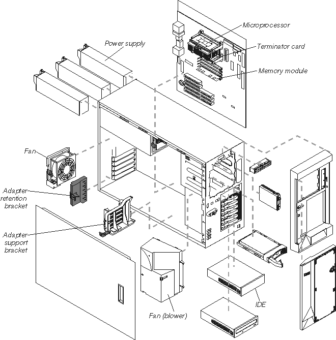
Figure 11 shows the locations of major components in your
appliance.
| Note: | The illustrations in this document might differ slightly from your
hardware.
|
Figure 11. Locations of major components

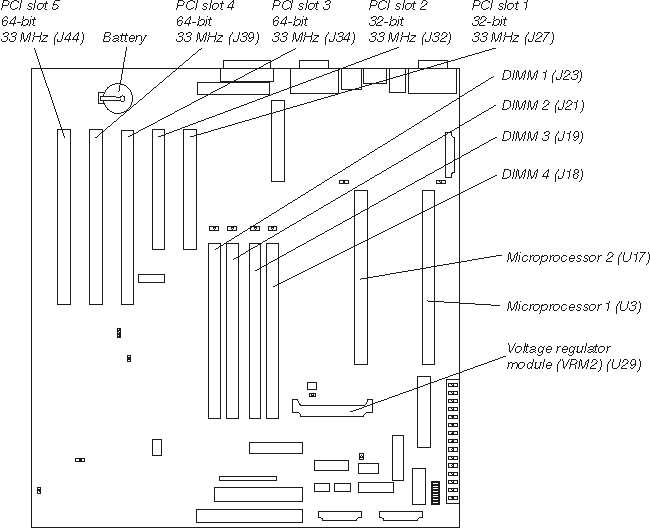
Figure 12 identifies system-board connectors for user-installable
options.
Figure 12. System-board options connectors

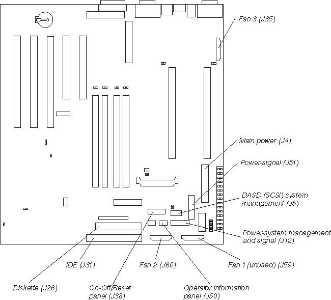
Figure 13 identifies system-board connectors for internal
cables.
Figure 13. System-board internal cable connectors

Figure 14 identifies the switches and jumpers on the system
board.
Figure 14. System board switches and jumpers
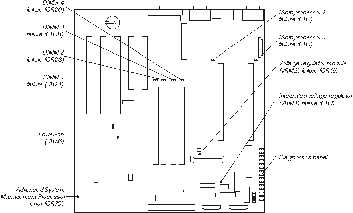
Figure 15 identifies system-board LEDs. You might need to refer
to this figure when troubleshooting a problem.
Figure 15. System board LED locations

| Note: | The power-on indicator (CR56) is on when system power is present in the
appliance. When this LED flashes, the appliance is in standby mode (the
system power supply is turned off and current is present).
|
Diagnostics panel LEDs:
- PS1
- Power supply 1 failure.
- PS2
- Power supply 2 failure.
- PS3
- Power supply 3 failure.
- NON
- Non-redundant power.
- OVER
- Overspec. The system has exceeded the power capabilities of the
installed power supply units.
- NMI
- Non-maskable-interrupt occurred.
- TEMP
- System temperature exceeded maximum rating.
- FAN
- A fan failed or is operating slowly.
- MEM
- Memory failure. One or more memory DIMMS have failed.
- CPU
- Microprocessor failure. One or both microprocessors have
failed.
- PCI A
- Error on PCI channel A or system board.
| Note: | PCI bus A is often referred to as PCI bus 0.
|
- PCI B
- Error on PCI channel B or system board.
| Note: | PCI bus B is often referred to as PCI bus 1.
|
- VRM
- Error on voltage regulator module or on integrated voltage
regulator.
- DASD1
- A hot-swap disk drive, backplane, or other part of SCSI channel A has
failed.
| Note: | This light is disabled and will not be on.
|
- DASD2
- A SCSI device on SCSI channel B has failed.
| Note: | This light is disabled and will not be on.
|
See Appliance controls and indicators for illustrations of the various controls and indicators
on the IBM IP Storage.
[ Top of Page | Previous Page | Next Page | Table of Contents | Index ]