IBM TotalStorage(TM) Enterprise Storage Server(TM)
Subsystem Device Driver User's Guide
Document Number GC26-7442-01
| Note |
|---|
|
Before using this information and the product it supports, read the
information in Notices. |
Tenth Edition (November 2001)
This edition includes information that specifically applies to IBM ESS
Subsystem Device Driver (SDD):
- |Version 1 Release 3 Modification 1 Level 3 for AIX
|4.2.1, AIX 4.3.2, AIX 4.3.3, AIX
|5.1.0
- |Version 1 Release 3 Modification 0 Level 1 for HP-UX 11.00,
|HP-UX 11i
- |Version 1 Release 3 Modification 0 Level 1 for Solaris 2.6,
|Solaris 7, Solaris 8
- |Version 1 Release 3 Modification 1 Level 1 for Windows 2000 Service
|Pack 2 or higher
- |Version 1 Release 3 Modification 1 Level 0 for Windows NT 4.0
|Service Pack 3 or higher
|This edition also applies to all subsequent releases and
|modifications until otherwise indicated in new editions.
(C) Copyright International Business Machines Corporation 1999, 2001. All rights reserved.
U.S. Government Users Restricted Rights -- Use, duplication or disclosure restricted by GSA ADP Schedule Contract with IBM Corp.
Figures
Tables
About this book
Chapter 1. Overview of the Subsystem Device Driver
Chapter 2. SDD for an AIX host system
Chapter 3. SDD for a Windows NT host system
Chapter 4. SDD for a Windows 2000 host system
Chapter 5. SDD for a Hewlett-Packard host system
Chapter 6. SDD for a Sun host system
Chapter 7. Using the datapath commands
Statement of Limited Warranty
Notices
Glossary
Index
- Multipath connections between a host system and the disk storage in an ESS
- Output from the Display Data Path Device Configuration SMIT panel
- IBMdpo Driver 32-bit
- IBMdpo Driver 64-bit
- Publications in the ESS library
- Other IBM publications related to the ESS.
- Other IBM publications without order numbers
- ESS Web sites and descriptions
- SDD in the protocol stack
- Required number of successful I/O operations before SDD places a path in the open state
- AIX PTF required fixes
- Support for 32-bit and 64-bit applications
- SDD package file names
- Major files included in the SDD installation package
- List of previously installed filesets that are supported with nondisruptive installation
- Software support for HACMP/6000 in concurrent mode
- Software support for HAMCP/6000 in nonconcurrent mode
- Software support for HACMP/6000 in concurrent mode on AIX 5.1.0 (32-bit kernel only)
- Software support for HACMP/6000 in nonconcurrent mode on AIX 5.1.0 (32-bit kernel only)
- HACMP/6000 and supported SDD features
- SDD-specific SMIT panels and how to proceed
- SDD installation scenarios
- HP patches necessary for proper operation of SDD
- SDD components installed for HP host systems
- System files updated for HP host systems
- SDD commands and their descriptions for HP host systems
- SDD installation scenarios
- SDD package file names
- Solaris patches necessary for proper operation of SDD
- SDD components installed for Sun host systems
- System files updated for Sun host systems
- SDD commands and their descriptions for Sun host systems
- Commands
This book provides step-by-step procedures for you to
install, configure, and use the IBM(R) TotalStorage(TM) Enterprise Storage
Server(TM) (ESS) Subsystem Device Driver (SDD) on IBM AIX(R), HP, Sun,
Microsoft(R) Windows NT(R), and Microsoft Windows 2000 host
systems.
This book is intended for storage administrators, system programmers, and
performance and capacity analysts.
This book contains both information previously presented in the IBM TotalStorage Enterprise Storage Server Subsystem Device
Driver User's Guide Version 1 Release 3.0 (September 2001)
and major technical changes to that information. Technical changes are
indicated by revision bars (|) in the left margin of the book. The
following sections summarize those technical changes.
- Note:
- For the last-minute changes that are not included in this book, see the
README file on the SDD compact disc or visit the SDD Web site at:
www.ibm.com/storage/support/techsup/swtechsup.nsf/support/sddupdates
This edition includes the following new
technical information:
What's new in Chapter 2, SDD for an AIX host system:
What's new in Chapter 5, SDD for a Hewlett-Packard host system:
This edition includes the following technical modified information:
What's modified in Chapter 2, SDD for an AIX host system:
- The SDD version release level for AIX is updated as follows:
- SDD 1.3.0.x t o SDD 1.3.1.3
This edition also includes the following organizational changes:
- The "Installing and configuring SDD on an AIX host system" and "Using SDD
on an AIX host system" chapters are consolidated into Chapter 2, SDD for an AIX host system.
- Other organizational changes made within the other chapters. These
changes are intended to help you find information easier and faster.
The tables in this section list and describe the following
publications:
- The publications that compose the IBM TotalStorage ESS library.
- Other IBM publications that relate to the ESS.
- non-IBM publications that relate to the ESS.
See Ordering ESS publications for information about how to order publications in the IBM
TotalStorage ESS publication library. See How to send your comments for information about how to send comments about the
publications.
Table 1 shows the customer publications that comprise the ESS
library. See The IBM publications center for information about ordering these and other IBM
publications.
Table 1. Publications in the ESS library
| Long title (short title)
| Description
| Order number
|
| IBM TotalStorage Enterprise Storage Server Copy
Services Command-Line Interface User's Guide (ESS CLI
User's Guide)
| This user's guide describes the commands you can use from the ESS
Copy Services command-line interface (CLI). The CLI application
provides a set of commands you can use to write customized scripts for a host
system. The scripts initiate pre-defined tasks in an ESS Copy Services
server application. You can use the CLI commands to indirectly control
ESS Peer-to-Peer Remote Copy and FlashCopy configuration tasks within an ESS
Copy Services server group.
This book is not available in hardcopy. It is available in PDF
format on the following Web site:
www.storage.ibm.com/hardsoft/products/ess/refinfo.htm
| SC26-7434
|
| IBM TotalStorage Enterprise Storage Server
Configuration Planner (ESS Configuration Planner)
| This guide provides work sheets for planning the logical configuration of
the ESS. This book is not available in hardcopy. This guide is
available on the following Web site:
www.storage.ibm.com/hardsoft/products/ess/refinfo.htm
| SC26-7353
|
| IBM TotalStorage Enterprise Storage Server Host
System Attachment Guide (ESS Attachment Guide)
| This book provides guidelines for attaching the ESS to your host system
and for migrating from Small Computer System Interface (SCSI) to fibre-channel
attachment.
| SC26-7296
|
| IBM TotalStorage Enterprise Storage Server DFSMS
Software Support Reference (ESS DFSMS Software Support)
| This book gives an overview of the ESS and highlights its unique
capabilities. It also describes Data Facility Storage Management
Subsystems (DFSMS) software support for the ESS, including support for large
volumes.
| SC26-7440
|
| IBM TotalStorage Enterprise Storage Server
Introduction and Planning Guide (ESS Introduction and Planning Guide)
| This guide introduces the ESS product and lists the features you can
order. It also provides guidelines for planning the installation and
configuration of the ESS.
| GC26-7294
|
| IBM TotalStorage Enterprise Storage Server Quick
Configuration Guide (ESS Quick Configuration Guide)
| This booklet provides flow charts for using the TotalStorage Enterprise
Storage Server Specialist (ESS Specialist). The flow charts provide a
high-level view of the tasks the IBM service support representative performs
during initial logical configuration. You can also use the flow charts
for tasks that you might perform when you are modifying the logical
configuration. The hardcopy of this booklet is a 9-inch ×
4-inch fanfold.
| SC26-7354
|
| IBM Enterprise Storage Server System/390 Command
Reference (ESS S/390 Command Reference)
| This book describes the functions of the ESS and provides reference
information for S/390(R) and  zSeries hosts, such as channel
commands, sense bytes, and error recovery procedures. zSeries hosts, such as channel
commands, sense bytes, and error recovery procedures.
| SC26-7298
|
| IBM TotalStorage Safety Notices (Safety
Notices)
| This book provides translations of the danger notices and caution notices
that IBM uses in ESS publications.
| GC26-7229
|
| IBM TotalStorage Enterprise Storage Server SCSI
Command Reference (ESS SCSI Command Reference)
| This book describes the functions of the ESS. It provides
reference information for UNIX(R), Application System/400(R)
(AS/400(R)), and iSeries 400 hosts, such as channel
commands, sense bytes, and error recovery procedures.
| SC26-7297
|
| IBM TotalStorage Enterprise Storage Server
User's Guide (ESS Users Guide)
| This guide provides instructions for setting up and operating the ESS and
for analyzing problems.
| SC26-7295
|
| IBM TotalStorage Enterprise Storage Server Web
Interface User's Guide (ESS Web Interface Users Guide)
| This guide provides instructions for using the two ESS Web interfaces,
ESS Specialist and ESS Copy Services.
| SC26-7346
|
All the customer publications that are listed in The IBM TotalStorage ESS library are available on a compact disc that comes with the ESS,
unless otherwise noted.
The customer documents are also available on the following ESS Web site in
PDF format:
www.storage.ibm.com/hardsoft/products/ess/refinfo.htm
The publications center is a worldwide central repository for IBM product
publications and marketing material.
The IBM publications center offers customized search functions to help you
find the publications that you need. A number of publications are
available for you to view or download free of charge. You can also
order publications. The publications center displays prices in your
local currency. You can access the IBM publications center through the
following Web site:
www.ibm.com/shop/publications/order/
The IBM publications center Web site offers you a notification system about
IBM publications. Register and you can create your own profile of
publications that interest you. The publications notification system
sends you daily electronic mail (e-mail) notes that contain information about
new or revised publications that are based on your profile.
If you want to subscribe, you can access the publications notification
system from the IBM publications center at the following Web site:
www.ibm.com/shop/publications/order/
Table 2 lists and describes other IBM publications that have
information.
Table 2. Other IBM publications related to the ESS.
| Title
| Description
| Order number
|
| DFSMS/MVS(R) Version 1 Advanced Copy Services,
| This publication helps you to understand and use IBM Advanced Copy
Services functions on an S/390 or zSeries. It describes two
dynamic-copy functions and several point-in-time copy functions. These
functions provide backup and recovery of data if a disaster occurs to your
data center. The dynamic-copy functions are Peer-to-Peer Remote Copy
and Extended Remote Copy. Collectively, these functions are known as
remote copy. FlashCopy(TM) and Concurrent Copy are the point-in-time
copy functions.
| SC35-0355
|
| DFSMS/MVS Version 1 Remote Copy Guide and Reference
| This publication provides guidelines for using remote copy functions with
S/390 and zSeries hosts.
| SC35-0169
|
| Enterprise Storage Solutions Handbook
| This book helps you understand what comprises enterprise storage
management. The concepts include the key technologies that you need to
know and the IBM subsystems, software, and solutions that are available
today. It also provides guidelines for implementing various enterprise
storage administration tasks, so that you can establish your own enterprise
storage management environment.
| SG24-5250
|
| ESS Fibre-Channel Migration Scenarios
| This white paper describes how to change your host system attachment to
the ESS from SCSI and SAN Data Gateway to native fibre-channel
attachment.
To get the white paper, go to the following Web site:
www.storage.ibm.com/hardsoft/products/ess/refinfo.htm
| No order number
|
| Enterprise Systems Architecture/390 ESCON I/O Interface
| This publication provides a description of the physical and logical
ESA/390 I/O interface and the protocols which govern information transfer over
that interface. It is intended for designers of programs and equipment
associated with the ESCON I/O interface and for service personnel maintaining
that equipment. However, anyone concerned with the functional details
of the ESCON I/O interface will find it useful.
| SA22-7202
|
| ESS Solutions for Open Systems Storage Compaq AlphaServer, HP, and
Sun
| This book helps you to install, tailor, and configure the ESS when you
attach Compaq AlphaServer (running Tru64 UNIX), HP, and Sun hosts. This
book does not cover Compaq AlphaServer running the Open VMS operating
system. This book also focuses on the settings required to give optimal
performance and on device driver levels. This book is for the
experienced UNIX professional who has a broad understanding of storage
concepts.
| SG24-6119
|
| Fibre Channel Connection (FICON) I/O Interface, Physical Layer
| This publication provides information to the Fiber Channel I/O
Interface. This book is also available in PDF format by accessing the
following Web site:
www.ibm.com/servers/resourcelink/
| SA24-7172
|
| Fibre-channel Subsystem Installation Guide
| This publication tells you how to attach the xSeries 430 and NUMA-Q host
system with fibre-channel adapters.
| See note.
|
| Fibre Transport Services (FTS) Direct Attach, Physical and
Configuration Planning Guide
| This publication provides information about fibre-optic and
ESCON-trunking systems.
| GA22-7234
|
| IBM Enterprise Storage Server
| This book, from the IBM International Technical Support Organization,
introduces the ESS and provides an understanding of its benefits. It
also describes in detail the architecture, hardware, and functions of the
ESS.
| SG24-5465
|
| IBM Enterprise Storage Server Performance Monitoring and Tuning
Guide
| This book provides guidance on the best way to configure, monitor, and
manage your ESS to ensure optimum performance.
| SG24-5656
|
| IBM OS/390 Hardware Configuration Definition User's Guide
| This publication provides detailed information about the IODF. It
also provides details about configuring parallel access volumes (PAVs).
OS/390 uses the IODF.
| SC28-1848
|
| IBM SAN Fibre Channel Managed Hub 3534 Service Guide
| The IBM SAN Fibre Channel Managed Hub can now be upgraded to switched
fabric capabilities with this Entry Switch Activation Feature. As your
fibre channel SAN requirements grow, and you need to migrate from the
operational characteristics of the Fibre Channel arbitrated loop (FC-AL)
configuration provided by the IBM Fibre Channel Managed Hub, 35341RU, to a
fabric capable switched environment, the Entry Switch Activation feature is
designed to provide this upgrade capability. This upgrade is designed
to allow a cost-effective, and scalable approach to developing fabric based
Storage Area Networks (SANs). The Entry Switch Activation feature (P/N
19P3126) supplies the activation key necessary to convert the FC-AL based
Managed Hub to fabric capability with eight fabric F_ports, one of which can
be an interswitch link-capable port, an E_port, for attachment to the IBM SAN
Fibre Channel Switch, or other supported switches.
| GC26-7391
|
| IBM SAN Fibre Channel Managed Hub 3534 Users Guide
| The IBM SAN Fibre Channel Switch 3534 is an eight-port Fibre Channel
Gigabit Hub that consists of a motherboard with connectors for supporting up
to eight ports, including seven fixed shortwave optic ports and one GBIC port,
and an operating system for building and managing a switched loop
architecture.
| SY27-7616
|
| IBM SAN Fibre Channel Switch, 2109 Model S08 Users Guide
| The IBM Fibre Channel Switch 2109 Model S08 Users Guide manual describes
the switch and the IBM StorWatch Specialist. It provides information on
the commands and how to manage the switch with Telnet and Simple Network
Management Protocol (SNMP).
To get a copy of this manual, see the Web site at:
www.ibm.com/storage/fcswitch
| SC26-7349
|
| IBM SAN Fibre Channel Switch 2109 Model S16 Installation and Service
Guide
| This publication describes how to install and maintain the IBM SAN Fibre
Channel Switch 2109 Model S16. It is intended for trained service
representatives and service providers who act as the primary level of field
hardware service support to help solve and diagnose hardware problems.
To get a copy of this manual, see the Web site at:
www.ibm.com/storage/fcswitch
| SC26-7352
|
| IBM StorWatch Expert Hands-On Usage Guide
| This guide helps you to install, tailor, and configure ESS Expert, and it
shows you how to use Expert.
| SG24-6102
|
| IBM TotalStorage
Enterprise Storage Server Subsystem Device Driver Installation and Users
Guide
| This book describes how to use the IBM Subsystem Device Driver on
open-systems hosts to enhance performance and availability on the ESS.
The Subsystem Device Driver creates redundant paths for shared logical unit
numbers. The Subsystem Device Driver permits applications to run
without interruption when path errors occur. It balances the workload
across paths, and it transparently integrates with applications.
For information about the Subsystem Device Driver, see the following Web
site:
www.ibm.com/storage/support/techsup/swtechsup.nsf/support/sddupdates/
| GC26-7442
|
| Implementing ESS Copy Services on S/390
| This publication tells you how to install, customize, and configure Copy
Services on an ESS that is attached to an S/390 or zSeries host system.
Copy Services functions include Peer-to-Peer Remote Copy, Extended Remote
Copy, FlashCopy(TM) and, Concurrent Copy. This publication describes
the functions, prerequisites, and corequisites and describes how to implement
each of the functions into your environment.
| SG24-5680
|
| Implementing ESS Copy Services on UNIX and Windows NT/2000
| This publication tells you how to install, customize, and configure ESS
Copy Services on UNIX or Windows NT host systems. Copy Services
functions include Peer-to-Peer Remote Copy, FlashCopy, Extended Remote Copy,
and Concurrent Copy. Extended Remote Copy and Concurrent Copy are not
available for UNIX and Windows NT host systems; they are only available
on the S/390 or zSeries. This publication describes the functions and
shows you how to implement each of the functions into your environment.
It also shows you how to implement these solutions in ahigh-availability
cluster multiprocessing (HACMP) cluster.
| SG24-5757
|
| Implementing Fibre Channel Attachment on the ESS
| This book helps you to install, tailor, and configure
fibre-channel attachment of open-systems hosts to the
ESS. It gives you a broad understanding of the procedures involved and
describes the prerequisites and requirements. It also shows you how to
implement fibre-channel attachment. This book also describes the
steps required to migrate to direct fibre-channel attachment from
native SCSI adapters and from fibre-channel attachment through the SAN
Data Gateway (SDG).
| SG24-6113
|
| Implementing the IBM Enterprise Storage Server
| This book can help you install, tailor, and configure the ESS in your
environment.
| SG24-5420
|
| NUMA-Q ESS Integration Release Notes for NUMA Systems
|
This publication provides information about special procedures and
limitations involved in running ESS with Copy Services on an IBM
xSeries 430 and an IBM NUMA-Q(R) host system.
It also provides information on how to:
- Configure the ESS
- Configure the IBM NUMA-Q and xSeries 430 host system
- Manage the ESS from the IBM NUMA-Q and xSeries 430 host system with
DYNIX/ptx tools
| Part number 1003-80094.
|
| OS/390 MVS System Messages Volume 1 (ABA - ASA)
| This publication lists OS/390 and zSeries MVS system messages ABA to
ASA.
| GC28-1784
|
| z/Architecture Principles of Operation
| This publication provides, for reference purposes, a detailed definition
of the z/Architecture. It is written as a reference for use primarily
by assembler language programmers and describes each function at the level of
detail needed to prepare an assembler language program that relies on that
function; although anyone concerned with the functional details of
z/Architecture will find it useful.
| SA22-7832
|
- Note:
- There is no order number for this publication. This publication is not
available through IBM ordering systems. Contact your sales
representative to obtain this publication.
Table 3 lists and describes other related publications that are not
available through IBM ordering systems. To order, contact the sales
representative at the branch office in your locality.
Table 3. Other IBM publications without order numbers
| Title
| Description
|
| Quick Start Guide: An Example with Network File System
(NFS)
| This publication tells you how to configure the Veritas Cluster
Server. See also the companion document, Veritas Cluster Server
User's Guide.
|
| Veritas Cluster Server Installation Guide
| This publication tells you how to install the Veritas Cluster
Server. See also the companion document, Veritas Cluster Server
Release Notes.
|
| Veritas Cluster Server Release Notes
| This publication tells you how to install the Veritas Cluster
Server. See also the companion document, Veritas Cluster Server
Installation Guide.
|
| Veritas Cluster Server User's Guide
| This publication tells you how to configure the Veritas Cluster
Server. See also the companion document, Quick Start Guide:
An Example with NFS.
|
| Veritas Volume Manager Hardware Notes
| This publication tells you how to implement dynamic multipathing.
|
| Veritas Volume Manager Installation Guide
| This publication tells you how to install VxVM. It is not
available through IBM ordering systems. Contact your sales
representative to obtain this document.
|
| Veritas Volume Manager Storage Administrators Guide
| This publication tells you how to administer and configure the disk
volume groups.
|
Table 4 shows Web sites that have information about the ESS and
other IBM storage products.
Table 4. ESS Web sites and descriptions
| Web site
| Description
|
| www.storage.ibm.com/
| This Web site has general information about IBM storage products.
|
| www.storage.ibm.com/hardsoft/products/ess/ess.htm
| This Web site has information about the IBM Enterprise Storage Server
(ESS).
|
| ssddom02.storage.ibm.com/disk/ess/documentation.html
| This Web site allows you to view and print the ESS publications.
|
| www.storage.ibm.com/hardsoft/products/ess/supserver.htm
| This Web site provides current information about the host system models,
operating systems, and adapters that the ESS supports.
|
| ssddom01.storage.ibm.com/techsup/swtechsup.nsf/support/sddupdates/
| This Web site provides information about the IBM Subsystem Device
Driver.
|
| www.storage.ibm.com/hardsoft/products/sangateway/sangateway.htm
| This Web site provides information about attaching Storage Area Network
or host system that uses an industry-standard, fibre-channel arbitrated loop
(FC-AL) topology through the IBM 2108 Storage Area Network Data Gateway Model
G07.
|
| www.storage.ibm.com/software/sms/sdm/sdmtech.htm
| This Web site provides information about the latest updates to Copy
Services components including XRC, PPRC, Concurrent Copy, and FlashCopy for
S/390 and zSeries.
|
| ssddom01.storage.ibm.com/techsup/swtechsup.nsf/support/sddcliupdates/
| This Web site provides information about the IBM ESS Copy Services
Command-Line Interface (CLI).
|
Your feedback is important to help us provide the highest quality
information. If you have any comments about this book or any other ESS
documentation, you can submit them in one of the following ways:
- e-mail
Submit your comments electronically to the following e-mail address:
starpubs@us.ibm.com
Be sure to include the name and order number of the book and, if
applicable, the specific location of the text you are commenting on, such as a
page number or table number.
- Mail or fax
Fill out the Readers' Comments form (RCF) at the back of this
book. Return it by mail or fax (1-800-426-6209) or give it to an IBM
representative. If the RCF has been removed, you may address your
comments to:
International Business Machines Corporation
RCF Processing Department
G26/050
5600 Cottle Road
San Jose, CA 95193-0001
U.S.A.
This chapter introduces the IBM TotalStorage Enterprise Storage Server
(ESS) Subsystem Device Driver (SDD) and provides an overview of SDD
functions.
The Subsystem Device Driver is a pseudo device driver designed to support
the multipath configuration environments in the IBM ESS. It resides in
a host system with the native disk device driver and provides the following
functions:
- Enhanced data availability
- Dynamic I/O load-balancing across multiple paths
- Automatic path failover protection
- Concurrent download of licensed internal code
- Path-selection policies for the host system
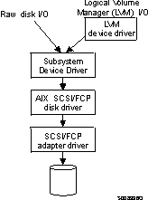
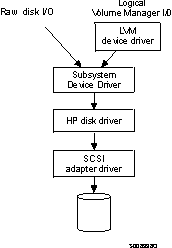
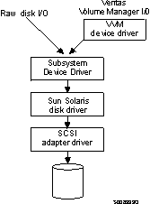
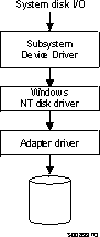
As the diagrams in Table 5 show, SDD resides above the disk driver of a host system in
the protocol stack and acts as a pseudo device driver. I/O operations
that are sent to SDD proceed to the host disk driver after path
selection. When an active path experiences a failure (such as a cable
or controller failure), SDD dynamically switches to another path.
Table 5. SDD in the protocol stack
Each SDD device represents a unique physical device on the storage
server. There can be up to 32 hdisk devices that represent up to 32
different paths to the same physical device.
SDD devices behave almost like hdisk devices. Most operations on an
hdisk device can be performed on the SDD device, including commands such as
open, close, dd, or fsck.
Figure 1 shows that an SDD-residing host system is attached
through SCSI or fibre-channel adapters to an ESS that has internal
component redundancy and multipath configuration. SDD uses this
multipath configuration to enhance data availability. That is, when
there is a path failure, SDD reroutes I/O operations from the failing path to
an alternate operational path. This capability prevents a single
failing bus adapter on the host system, SCSI or fibre-channel cable, or
host-interface adapter on the ESS from disrupting data access.
Figure 1. Multipath connections between a host system and the disk storage in an ESS
By distributing the I/O workload over multiple active paths, SDD provides
dynamic load-balancing and eliminates data-flow bottlenecks. In
the event of failure in one data path, SDD automatically switches the affected
I/O operations to another active data path, ensuring path-failover
protection.
The SDD failover protection system is designed to minimize any disruptions
in I/O operations and recover I/O operations from a failing data path.
SDD provides path-failover protection through the following
process:
- Detecting a path failure
- Notifying the host system of the path failure
- Selecting and using an alternate data path
SDD dynamically selects an alternate I/O path when it detects a software or
hardware problem.
With SDD you can concurrently download and install the licensed internal
code while applications continue running. During the download and
installation process, the host adapters inside the ESS might not respond to
host I/O requests for approximately 30 seconds. SDD makes this process
transparent to the host system through its path-selection and retry
algorithms.
SDD uses similar path-selection algorithms on all the host
systems. There are two modes of operation:
- single-path mode
- The host system has only one path that is configured to an ESS logical
unit number (LUN). SDD, in single-path mode, has the following
characteristics:
- When an I/O error occurs, SDD retries the I/O operation a sufficient
number of times to bypass the interval when the ESS host adapters are not
available. This I/O error might be caused by the process of
concurrently downloading licensed internal code. See Concurrent download of licensed internal code for more information.
- SDD never puts this single path into the dead state.
- multiple-path mode
- The host system has multiple paths that are configured to an ESS
LUN. SDD in multiple-path mode has the following characteristics:
This chapter provides step-by-step procedures for you to
install, configure, upgrade, and remove the Subsystem Device Driver on an AIX
host system that is attached to an ESS.
You must install the following hardware and software components to ensure
that SDD installs and operates successfully.
- Hardware
-
- ESS
- Host system
- SCSI adapters and cables
- Fibre adapters and cables
- Software
-
- ibm2105.rte ESS package
- AIX operating system
- SCSI and fibre-channel device drivers
SDD does not support the following environments:
- A host system with a single-path fibre-channel connection to an ESS
- Note:
- A host system with a single fibre-channel adapter that connects through a
switch to multiple ESS ports is considered a multipath fibre-channel
connection; and, thus is a supported environment.
- A host system with both a SCSI and fibre-channel connection to a shared
ESS LUN
- SDD does not support a system restart from an SDD pseudo device.
- SDD does not support placing system paging devices (for example, /dev/hd6)
on an SDD pseudo device.
- |SDD 1.3.1.3 installed from the
|ibmSdd_421.rte, ibmSdd_432.rte and ibmSdd_510.rte
|filesets do not support any application that depends on a SCSI reserve and
|release device on AIX 4.2.1, AIX 4.3.2, AIX
|4.3.3, and A,IX 5.10.
|To successfully install SDD 1.3.1.3, you must
|have AIX 4.2.1, AIX 4.3.2, AIX 4.3.3
|or AIX 5.1.0 installed on your host system along with the fixes
|in Table 7.
|
|Table 7. AIX PTF required fixes
| AIX level
| PTF number
| Component name
| Component level
|
| 4.2.1
| IX62304
|
|
|
| U451711
| perfagent.tools
| 2.2.1.4
|
| U453402
| bos.rte.libc
| 4.2.1.9
|
| U453481
| bos.adt.prof
| 4.2.1.11
|
| U458416
| bos.mp
| 4.2.1.15
|
| U458478
| bos.rte.tty
| 4.2.1.14
|
| U458496
| bos.up
| 4.2.1.15
|
| U458505
| bos.net.tcp.client
| 4.2.1.19
|
| U462492
| bos.rte.lvm
| 4.2.1.16
|
| 4.3.2
| U461953
| bos.rte.lvm
| 4.3.2.4
|
|
|
|
Attention: You must check for the latest information on
APARs, maintenance level fixes, and microcode updates at the following Web
site:
service.software.ibm.com/support/rs6000
To successfully install SDD, ensure that your ESS meets the following
requirements:
- The ibm2105.rte ESS package must be installed on your AIX host
system.
- The ESS devices must be configured as either an:
- IBM 2105xxx (SCSI-channel attached device)
- IBM FC 2105xxx (fibre-channel attached device)
- Note:
- xxx is the ESS model number.
To use the SDD SCSI support, ensure your host system meets the following
requirements:
- The bos.adt package must be installed. The host system can
be a uniprocessor or a multiprocessor system, such as SMP.
- A SCSI cable is required to connect each SCSI host adapter to an ESS
port.
- The SDD I/O load-balancing and failover features require a minimum of two
SCSI adapters.
- Note:
- SDD also supports one SCSI adapter on the host system. With
single-path access, concurrent download of licensed internal code is supported
with SCSI devices.
For information about the SCSI adapters that can attach to your AIX host
system, go to the following Web site:
www.storage.ibm.com/hardsoft/products/ess/supserver.htm
Attention: You must check for the latest information on
fibre-channel device driver APARs, maintenance level fixes, and microcode
updates at the following Web site:
|techsupport.services.ibm.com/server/fixes
To use the SDD fibre support, ensure your host system meets the following
requirements:
- The AIX host system is an IBM RS/6000(R) with AIX 4.3.3
or AIX 5.1.0.
- The AIX host system has the fibre-channel device drivers
installed along with APARs.
- The bos.adt package must be installed. The host system can
be a uniprocessor or a multiprocessor system, such as SMP.
- A fiber-optic cable is required to connect each fibre-channel adapter to
an ESS port.
- |The Emulex LP70000E and LP9002 adapters should be attached to its
|own PCI bus. These adapters should not be shared with other PCI
|adapters.
- |Note:
- Emulex LP9002 is supported with AIX 4.3.3.50 (or later)
|maintenance level only.
|
|Attention: If more than one adapter is attached to a
|peripheral component interconnect (PCI) bus, both adapter devices will be
|configured. Sometimes, though, one adapter saturates the entire PCI bus
|and causes command timeouts.
- The SDD I/O load-balancing and failover features require a minimum of two
paths to a device.
For information about the fibre-channel adapters that can be used on your
AIX host system go to the following Web site:
|www-1.ibm.com/servers/eserver/pseries/library/hardware_docs/
|Table 8 summarizes SDD 1.3.1.3
|support for 32-bit and 64-bit applications on AIX 4.3.2, AIX
|4.3.3, and AIX 5.1.0.
|
|Table 8. Support for 32-bit and 64-bit applications
| SDD Installation Filesets
| Application Mode
| SDD Interface
| AIX Kernel Mode
| SDD Support
|
| ibmSdd_432.rte
| 32-bit, 64-bit
| LVM, raw device
| 32-bit
| Yes
|
| ibmSdd_433.rte
| 32-bit, 64-bit
| LVM, raw device
| 32-bit
| Yes
|
| ibmSdd_510.rte
| 32-bit, 64-bit
| LVM, raw device
| 32-bit, 64-bit
| Yes
|
| ibmSdd_510nchacmp.rte
| 32-bit, 64-bit
| LVM, raw device
| 32-bit, 64-bit
| Yes
|
|SDD 1.3.1.3 supports AIX 5.1.x
|host systems that run in both 32-bit and 64-bit kernel
|modes. You can use the bootinfo -K or ls
|-al /unix command to check the current kernel mode in which your
|AIX 5.1.x host system is running.
The bootinfo -K command directly returns the kernel mode
information of your host system. The ls -al /unix
command displays the /unix link information. If the
/unix links to /usr/lib/boot/unix_mp, your AIX
5.1.x host system runs in 32-bit mode. If the
/unix links to /usr/lib/boot/unix_64, your AIX
5.1.x host system runs in 64-bit mode.
If your host system is currently running in 32-bit mode, you can
switch it to 64-bit mode by typing the following commands in the given
order:
ln -sf /usr/lib/boot/unix_64 /unix
ln -sf /usr/lib/boot/unix_64 /usr/lib/boot/unix
bosboot -ak /usr/lib/boot/unix_64
shutdown -Fr
The kernel mode of your AIX host system is switched to 64-bit mode
after the system restart completes. As a result, SDD automatically
switches to 64-bit mode.
If your host system is currently running in 64-bit mode, you can
switch it to 32-bit mode by typing the following commands in the given
order:
ln -sf /usr/lib/boot/unix_mp /unix
ln -sf /usr/lib/boot/unix_mp /usr/lib/boot/unix
bosboot -ak /usr/lib/boot/unix_mp
shutdown -Fr
The kernel mode of your AIX host system is switched to 32-bit mode
after the system restart completes. As a result, SDD automatically
switches to 32-bit mode.
Before you install SDD, you must configure the ESS to your host system and
the required fibre-channel adapters.
Before you install SDD, configure your ESS for single-port or multiple-port
access for each LUN. SDD requires a minimum of two independent paths
that share the same logical unit to use the load-balancing and failover
features.
For more information about configuring your IBM Enterprise Storage Server,
see IBM TotalStorage Enterprise Storage Server
Introduction and Planning Guide.
- Note:
- Ensure the ibm2105.rte installation package is installed.
Attention: You must check for the latest information on
fibre-channel device driver APARs, maintenance level fixes, and microcode
updates at the following Web site:
|techsupport.services.ibm.com/server/fixes
AIX fibre-channel device drivers are developed by IBM for the Emulex
LP7000E adapter.
This section contains the procedures for installing fibre-channel device
drivers and configuring fibre-channel devices. These procedures
include:
- Installing the AIX fibre-channel device drivers
- Installing the Emulex adapter firmware
- Configuring fibre-channel attached devices
This section also contains procedures for:
- Removing fibre-channel attached devices
- Uninstalling fibre-channel device drivers
Requirement: For the fibre-channel support, the AIX host
system must be an IBM RS/6000 system with AIX 4.3.3 or AIX
5.1.0. The AIX host system should have the fibre-channel
device driver installed along with all APARs.
Attention: You must check for the latest information on
fibre-channel device driver APARs, maintenance level fixes, and microcode
updates at the following Web site:
|techsupport.services.ibm.com/server/fixes
Perform the following steps to install the AIX fibre-channel device
drivers:
- Install the fibre-channel device drivers from the AIX 4.3.3
compact disc. The fibre-channel device drivers include the following
filesets:
- |devices.pci.df1000f9
- |The adapter device driver for RS/6000 with feature code 6228.
- devices.pci.df1000f7
- The adapter device driver for RS/6000 with feature code 6227.
- devices.common.IBM.fc
- The FCP and SCSI protocol driver.
- devices.fcp.disk
- The FCP disk driver.
- Check to see if the correct APARS are installed by issuing the
instfix -i | grep IY nnnnn command (where
nnnnn represents the APAR numbers). If the APARS are listed,
that means that they are installed. If they are installed, go to Configuring fibre-channel attached devices. Otherwise, go to step 3.
- Install the APARS.
The following steps describe how to uninstall the AIX fibre-channel device
drivers. There are two methods for uninstalling all of your
fibre-channel device drivers. You can:
- Issue the smitty deinstall command.
- Manually uninstall the drivers using the installp
command.
Perform the following steps to use the smitty deinstall
command:
- Type smitty deinstall at the AIX command prompt and press
Enter. The Remove Installed Software panel is displayed.
- Press F4. All of the software that is installed is
displayed.
- Select the file name of the fibre-channel device driver you want to
uninstall. Press Enter. The selected file name is displayed in
the Software Name Field of the Remove Installed Software
panel.
- Use the Tab key to toggle to No in the PREVIEW Only?
field. Press Enter. The uninstallation process begins.
Perform the following steps to use the installp command from the
AIX command line:
- |Type installp -ug devices.pci.df1000f9 and
|press Enter.
- Type installp -ug devices.pci.df1000f7 and press
Enter.
- Type installp -ug devices.common.IBM.fc
and press Enter.
- Type installp -ug devices.fcp.disk and press
Enter.
The newly installed devices must be configured before they can be
used. There are two ways to configure these devices. You
can:
- Issue the cfgmgr command.
- Issue the shutdown -rF command to restart the system.
After the system restarts, use the lsdev -Cc disk command to check
the ESS fibre-channel protocol (FCP) disk configuration. If the FCP
devices are configured correctly, they should be in the Available
state. If the FCP devices are configured correctly, go to Determining the Emulex adapter firmware level to determine if the proper firmware level is
installed.
To remove all fibre-channel attached devices, you must issue the
rmdev -dl fcsN -R command for each installed FCP adapter,
where N is the FCP adapter number. For example, if you have
two installed FCP adapters (adapter 0 and adapter 1), you must issue both the
commands: rmdev -dl fcs0 -R and the rmdev -dl
fcs1 -R.
You are required to upgrade to a new adapter firmware if your current
adapter firmware is not at the latest level.
|Tip:
|
- |The current firmware level for Emulex LP7000E adapter is sf322A0.
- |The current firmware level for Emulex LP9002 adapter is sf382A0.
|
|.
|Perform the following steps to determine the Emulex adapter LP7000E
|firmware level:
|
- |Determine the firmware level that is currently installed. Issue the
|
|
|lscfg -vl fcsN command. The adapter's vital product
|data is displayed.
- |Look at the ZB field. The ZB field should
|look something like this:
|+--------------------------------------------------------------------------------+
||(ZB).............S2F3.22A0                                                      |
|+--------------------------------------------------------------------------------+
|To determine the firmware level, ignore the second character in the
|ZB field. In the example, the firmware level is
|sf322A0.
- |If the adapter firmware level is at the latest level, there is no need to
|upgrade; otherwise, the firmware level must be upgraded. To
|upgrade the firmware level, go to Upgrading the Emulex adapter firmware level.
|
Upgrading the firmware level consists of downloading the firmware
(microcode) from your AIX host system to the adapter. Before this can
be done, however, the fibre-channel attached devices must be
configured. After the devices are configured, you are ready to download
the firmware from the AIX host system to the FCP adapter. Perform the
following steps to download the firmware:
- Verify that the correct level of firmware is installed on your AIX host
system. Locate the file called
df1000f7.131.320.320.320.503. It
should be in the /etc/microcode directory. This file was copied into
the /etc/microcode directory during the installation of the fibre-channel
device drivers.
- From the AIX command prompt, type diag and press Enter.
- Select the Task Selection option.
- Select the Download Microcode option.
- Select all the fibre-channel adapters to which you want to download
firmware. Press F7. The Download panel is displayed with one of
the selected adapters highlighted. Press Enter to continue.
- Type the filename for the firmware that is contained in the /etc/microcode
directory and press Enter; or use the Tab key to toggle to
Latest.
- Follow the instructions that are displayed to download the firmware, one
adapter at a time.
- After the download is complete, issue the lscfg -v -l
fcsN command to verify the firmware level on each
fibre-channel adapter.
You must have root access and AIX system administrator knowledge to install
SDD.
To install SDD, use the installation package that is appropriate for your
environment. Table 9 lists and describes the SDD installation package file names
(filesets).
Table 9. SDD package file names
| Package file names
| Description
|
| ibmSdd_421.rte
| AIX 4.2.1
|
| ibmSdd_432.rte
| AIX 4.3.2 or AIX 4.3.3
(also use when running HACMP with AIX 4.3.3 in concurrent
mode)
|
| ibmSdd_433.rte
| AIX 4.3.3
(only use when running HACMP with AIX 4.3.3 in nonconcurrent
mode)
|
| ibmSdd_510.rte
| AIX 5.1.0
(also use when running HACMP with AIX 5.1.0 in concurrent
mode)
|
| ibmSdd_510nchacmp.rte
| AIX 5.1.0
(also use when running HACMP with AIX 5.1.0 in nonconcurrent
mode)
|
SDD is released as an installation image. The fileset name is
ibmSdd_nnn.rte, where nnn represents the AIX version level
(4.2.1, 4.3.2, 4.3.3 or
5.1.0). For example, the fileset name for the AIX
4.3.2 level is ibmSdd_432.rte.
- Note:
- The ibmSdd_432.rte installation package can be installed on an AIX
4.3.2 or AIX 4.3.3 system.
|SDD 1.3.1.3 installed from either the
|ibmSdd_432.rte or ibmSdd_433.rte fileset is a 32-bit
|device driver. This version supports 32-bit and 64-bit mode
|applications on AIX 4.3.2 and AIX 4.3.3 host
|systems. A 64-bit mode application can access an SDD device
|directly or through the logical volume manager (LVM). SDD
|1.3.1.3 installed from the ibmSdd_433.rte fileset
|is supported on AIX 4.3.3 and is for HACMP/6000 environments
|only. For more information about HACMP/6000, see Understanding the SDD support for High Availability Cluster Multi-Processing (HACMP/6000). It supports nonconcurrent and concurrent
|modes. However, in order to make the best use of the manner in which
|the device reserves are made, IBM recommends that you:
|
- |Use the ibmSdd_432.rte fileset for SDD 1.3.1.3
|when running HACMP with AIX 4.3.3 in concurrent mode.
- |Use the ibmSdd_433.rte fileset for SDD 1.3.1.3
|when running HACMP with AIX 4.3.3 in nonconcurrent mode.
|
|Table 9 lists and describes the installation package file
|names (filesets) for the SDD 1.3.1.3. For more
|information about HACMP, see Understanding the SDD support for High Availability Cluster Multi-Processing (HACMP/6000).
|The 1.3.1.3 version of the SDD installed from
|either ibmSdd_510.rte or ibmSdd_510nchacmp.rte filesets are
|supported on AIX 5.1.0. It contains both 32-bit and
|64-bit drivers. Based on the kernel mode currently running on the
|system, the AIX loader will load the correct mode of the SDD into the
|kernel. SDD 1.3.1.3 contained in the
|ibmSdd_510nchacmp.rte fileset supports HACMP/6000 in both concurrent
|and nonconcurrent modes. IBM recommends that you:
|
- |Install SDD 1.3.1.3 from the ibmSdd_510.rte
|fileset if you run HACMP with AIX 5.1.0 in concurrent code
|only.
- |Install SDD 1.3.1.3 from the
|ibmSdd_510nchacmp.rte fileset if you run HACMP with AIX
|5.1.0 in nonconcurrent mode.
|
|
|
The published AIX limitation on one system is 10,000 devices. The
combined number of hdisk and vpath devices should not exceed the number of
supported devices by AIX. In a multipath environment, since each path
to a disk creates an hdisk, the total number of disks being configured can be
reduced by the number of paths to each disk.
The installation package installs a number of major files on your AIX
system.Table 10 lists the major files that are part of the SDD installation
package.
Table 10. Major files included in the SDD installation package
| Filename
| Description
|
| defdpo
| Define method of the SDD pseudo parent data path optimizer (dpo)
|
| cfgdpo
| Configure method of the SDD pseudo parent dpo
|
| define_vp
| Define method of the SDD vpath devices
|
| addpaths
| The command that dynamically adds more paths to Subsystem Device Driver
devices while they are in Available state.
- Note:
- This command is not supported with Subsystem Device Driver for AIX
4.2.1; It is not available if you have the
ibmSdd_421.rte fileset installed. This feature only supports
Subsystem Device Driver for AIX 4.3.2 and higher.
|
| cfgvpath
| Configure method of SDD vpath devices
|
| cfallvpath
| Fast-path configure method to configure the SDD pseudo parent dpo and all
vpath devices.
|
| vpathdd
| SDD
|
| hd2vp
| The SDD script that converts an ESS hdisk device volume group to a
Subsystem Device Drive vpath device volume group.
|
| vp2hd
| The SDD script that converts a SDD vpath device volume group to an ESS
hdisk device volume group.
|
| datapath
| The SDD driver console command tool.
|
| lsvpcfg
| The SDD driver query configuration status command.
|
| mkvg4vp
| The command that creates a SDD volume group.
|
| extendvg4vp
| The command that extends SDD devices to a SDD volume group.
|
| dpovgfix
| The command that fixes a SDD volume group that has mixed vpath and hdisk
physical volumes.
|
| savevg4vp
| The command that backs-up all files belonging to a specified volume group
with SDD devices.
|
| restvg4vp
| The command that restores all files belonging to a specified volume group
with SDD devices.
|
The following procedures assume that SDD will be used to access all of your
single and multipath devices.
|Use the SMIT facility to install SDD. The SMIT facility has two
|interfaces, nongraphical (type smitty to invoke the nongraphical
|user interface) or graphical (type smit to invoke the graphical
|user interface).
- |Note:
- The list items on the SMIT panel might be worded differently from one AIX
|version to another.
|
Throughout this SMIT procedure, /dev/cd0 is used for the compact disc drive
address. The drive address can be different in your environment.
Perform the following SMIT steps to install the SDD package on your
system.
- Log in as the root user.
- Load the compact disc into the CD-ROM drive.
- From your desktop window, type smitty install_update and press
Enter to go directly to the installation panels. The Install and Update
Software menu is displayed.
- Highlight Install Software and press Enter.
- Press F4 to display the INPUT Device/Directory for Software panel.
- Select the compact disc drive that you are using for the
installation; for example, /dev/cd0, and press Enter.
- Press Enter again. The Install Software panel is displayed.
- Highlight Software to Install and press F4. The Software
to Install panel is displayed.
- Select the installation package that is appropriate for your
environment. Table 9 lists and describes the SDD installation package
file names (filesets).
- Press Enter. The Install and Update from LATEST Available Software
panel is displayed with the name of the software you selected to
install.
- Check the default option settings to ensure that they are what you
need.
- Press Enter to install. SMIT responds with the following
message:
+--------------------------------------------------------------------------------+
|     ARE YOU SURE??                                                             |
|     Continuing may delete information you may want to keep.                    |
|     This is your last chance to stop before continuing.                        |
+--------------------------------------------------------------------------------+
- Press Enter to continue. The installation process can take several
minutes to complete.
- When the installation is complete, press F10 to exit from SMIT.
Remove the compact disc.
You can verify your currently installed version of the SDD by issuing one
of the following commands:
lslpp -l ibmSdd_421.rte
lslpp -l ibmSdd_432.rte
lslpp -l ibmSdd_433.rte
lslpp -l ibmSdd_510.rte
lslpp -l ibmSdd_510nchacmp.rte
If you have successfully installed the ibmSdd_432.rte
package, the output from the lslpp -l ibmSdd_432.rte command
looks like this:
|+--------------------------------------------------------------------------------+
||Fileset                      Level  	 State        Description                  |
||------------------------------------------------------------------------------  |
||Path: /usr/lib/objrepos                                                         |
||  ibmSdd_432.rte             1.3.1.3  COMMITTED    IBM Subsystem Device Driver  |
||                                                   AIX V432 V433 for concurrent |
||                                                   HACMP                        |
||                                                                                |
||Path: /etc/objrepos                                                             |
||  ibmSdd_432.rte             1.3.1.3  COMMITTED    IBM Subsystem Device Driver  |
||                                                   AIX V432 V433 for concurrent |
||                                                   HACMP                        |
||                                                                                |
|+--------------------------------------------------------------------------------+
If you have successfully installed the ibmSdd_433.rte
package, the output from the lslpp -l ibmSdd_433.rte command
looks like this:
|+--------------------------------------------------------------------------------+
||Fileset                      Level  	 State        Description                  |
||--------------------------------------------------------------------------------|
||Path: /usr/lib/objrepos                                                         |
||  ibmSdd_433.rte             1.3.1.3  COMMITTED    IBM Subsystem Device Driver  |
||                                                   AIX V433  for nonconcurrent  |
||                                                   HACMP                        |
||                                                                                |
||Path: /etc/objrepos                                                             |
||  ibmSdd_433.rte             1.3.1.3  COMMITTED    IBM Subsystem Device Driver  |
||                                                   AIX V433  for nonconcurrent  |
||                                                   HACMP                        |
||                                                                                |
|+--------------------------------------------------------------------------------+
If you have successfully installed the ibmSdd_510.rte
package, the output from the lslpp -l ibmSdd_510.rte command
looks like this:
|+--------------------------------------------------------------------------------+
||Fileset                      Level  	 State        Description                  |
||--------------------------------------------------------------------------------|
||Path: /usr/lib/objrepos                                                         |
||  ibmSdd_510.rte             1.3.1.3  COMMITTED    IBM Subsystem Device Driver  |
||                                                   AIX V510 for concurrent HACMP|
||                                                                                |
||Path: /etc/objrepos                                                             |
||  ibmSdd_510.rte             1.3.1.3  COMMITTED    IBM Subsystem Device Driver  |
||                                                   AIX V510 for concurrent HACMP|
||                                                                                |
|+--------------------------------------------------------------------------------+
If you have successfully installed the
ibmSdd_510nchacmp.rte package, the output from the
lslpp -l ibmSdd_510nchacmp.rte command looks like
this:
|+--------------------------------------------------------------------------------+
||Fileset                      Level    State        Description                  |
||--------------------------------------------------------------------------------|
||Path: /usr/lib/objrepos                                                         |
||  ibmSdd_510nchacmp.rte      1.3.1.3  COMMITTED    IBM Subsystem Device Driver  |
||                                                   AIX V510 for nonconcurrent   |
||                                                   HACMP                        |
||                                                                                |
||Path: /etc/objrepos                                                             |
||  ibmSdd_510nchacmp.rte      1.3.1.3  COMMITTED    IBM Subsystem Device Driver  |
||                                                   AIX V510 for nonconcurrent   |
||                                                   HACMP                        |
||                                                                                |
|+--------------------------------------------------------------------------------+
Before you configure SDD, ensure that:
- The ESS is operational.
- The ibmSdd_nnn.rte software is installed on the AIX host
system.
- The ESS hdisks are configured correctly on the AIX host system.
Configure the ESS devices before you configure the SDD. If you
configure multiple paths to an ESS device, make sure that all paths (hdisks)
are in Available state. Otherwise, some SDD devices will
lose multiple-path capability.
Perform the following steps:
- Issue the lsdev -Cc disk | grep 2105 command to check the
ESS device configuration.
- If you have already created some ESS volume groups, vary off (deactivate)
all active volume groups with ESS subsystem disks by using the
varyoffvg (LVM) command.
Attention: Before you vary off a volume group, unmount all
file systems in that volume group. If some ESS devices (hdisks) are
used as physical volumes of an active volume group, and there are file systems
of that volume group being mounted, then you must unmount all file systems,
and vary off (deactivate) all active volume groups with ESS SDD disks.
Perform the following steps to configure SDD using SMIT:
- Note:
- |The list items on the SMIT panel might be worded differently from
|one AIX version to another.
|
- Type smitty device from your desktop window. The Devices
menu is displayed.
- Highlight Data Path Device and press Enter. The Data
Path Device panel is displayed.
- Highlight Define and Configure All Data Path Devices and press
Enter. The configuration process begins.
- Check the SDD configuration status. See Displaying the ESS vpath device configuration.
- Enter the varyonvg command to vary on all deactivated ESS
volume groups.
- If you want to convert the ESS hdisk volume group to SDD vpath devices,
you must run the hd2vp utility. (See hd2vp and vp2hd for information about this utility.)
- Mount the file systems for all volume groups that were previously
unmounted.
Before you unconfigure SDD devices, ensure that:
- |All I/O activities on the devices that you need to unconfigure are
|stopped.
- All file systems belonging to the SDD volume groups are umounted.
Then, run the vp2hd conversion script to convert the volume group from SDD
devices (vpathN) to ESS devices (hdisks).
- Note:
- |If you are running HACMP with ibmSdd_433.rte or
|ibmSdd_510nchacmp.rte fileset installed on your host system, there are
|special requirements regarding unconfiguring and removing SDD
|1.3.1.3. vpath devices. See Special requirements.
|
|
Using SMIT, you can unconfigure the SDD devices in two ways. Either
you can unconfigure without deleting the device information from
the Object Database Management (ODM) database, or you can delete
device information from the ODM database. If you unconfigure
without deleting the device information, the device remains in the
Defined condition. Using either SMIT or the mkdev -l vpathN
command, you can return the device to the Available condition.
If you delete the device information from the ODM database, that device is
removed from the system. To return it, follow the procedure described
in "Configuring the Subsystem Device Driver".
Perform the following steps to unconfigure SDD devices:
- Note:
- |The list items on the SMIT panel might be worded differently from
|one AIX version to another.
|
- Type smitty device from your desktop window. The Devices
menu is displayed.
- Highlight Devices and press Enter. The Devices menu is
displayed.
- Highlight Data Path Device and press Enter. The Data
Path Device panel is displayed.
- Highlight Remove a Data Path Device and press Enter. A
list of all SDD devices and their conditions (either Defined or Available) is
displayed.
- Select the device that you want to unconfigure. Select whether or
not you want to delete the device information from the ODM database.
- Press Enter. The device is unconfigured to the condition that you
selected.
- To unconfigure more SDD devices you have to repeat steps 4-6 for each SDD
device.
The fast-path command to unconfigure all SDD devices from the
Available to the Defined condition is: rmdev -l dpo
-R. The fast-path command to remove all Subsystem
Device Driver devices from your system is: rmdev -dl dpo
-R.
To check the SDD configuration, you can use either the SMIT Display Device
Configuration panel or the lsvpcfg console command.
Perform the following steps to verify the SDD configuration on an AIX host
system:
- Note:
- |The list items on the SMIT panel might be worded differently from
|one AIX version to another.
|
- Type smitty device from your desktop window. The Devices
menu is displayed.
- Select Data Path Device and press Enter. The Data Path
Device panel is displayed.
- Select Display Data Path Device Configuration and press Enter
to display the condition (Defined or Available) of all
SDD pseudo devices and the paths to each device.
If any device is listed as Defined, the configuration was not
successful. Check the configuration procedure again. See Configuring the Subsystem Device Driver for information about the procedure.
Perform the following steps to verify that multiple paths are configured
for each adapter connected to an ESS port:
- Type smitty device from your desktop window. The Devices
menu is displayed.
- Highlight Data Path Device and press Enter. The Data
Path Device panel is displayed.
- Highlight Display Data Path Device Adapter Status and press
Enter. All attached paths for each adapter are displayed.
If you want to use the command-line interface to verify the configuration,
type lsvpcfg.
You should see an output similar to this:
+--------------------------------------------------------------------------------+
|vpath0 (Avail pv vpathvg) 018FA067 = hdisk1 (Avail )                            |
|vpath1 (Avail ) 019FA067 = hdisk2 (Avail )                                      |
|vpath2 (Avail ) 01AFA067 = hdisk3 (Avail )                                      |
|vpath3 (Avail ) 01BFA067 = hdisk4 (Avail ) hdisk27 (Avail )                     |
|vpath4 (Avail ) 01CFA067 = hdisk5 (Avail ) hdisk28 (Avail )                     |
|vpath5 (Avail ) 01DFA067 = hdisk6 (Avail ) hdisk29 (Avail )                     |
|vpath6 (Avail ) 01EFA067 = hdisk7 (Avail ) hdisk30 (Avail )                     |
|vpath7 (Avail ) 01FFA067 = hdisk8 (Avail ) hdisk31 (Avail )                     |
|vpath8 (Avail ) 020FA067 = hdisk9 (Avail ) hdisk32 (Avail )                     |
|vpath9 (Avail pv vpathvg) 02BFA067 = hdisk20 (Avail ) hdisk44 (Avail )          |
|vpath10 (Avail pv vpathvg) 02CFA067 = hdisk21 (Avail ) hdisk45 (Avail )         |
|vpath11 (Avail pv vpathvg) 02DFA067 = hdisk22 (Avail ) hdisk46 (Avail )         |
|vpath12 (Avail pv vpathvg) 02EFA067 = hdisk23 (Avail ) hdisk47 (Avail )         |
|vpath13 (Avail pv vpathvg) 02FFA067 = hdisk24 (Avail ) hdisk48 (Avail )         |
+--------------------------------------------------------------------------------+
The output shows:
- The name of each pseudo device (for example, vpath13)
- The Defined or Available condition of a pseudo device
- Whether or not the pseudo device is defined to AIX as a physical volume
(the pv flag)
- The name of the volume group the device belongs to (for example,
vpathvg)
- The unit serial number of the ESS LUN (for example, 02FFA067)
- The names of the AIX disk devices making up the pseudo device and their
configuration and physical volume status
SDD supports path-selection policies that increase the performance of a
multipath-configured ESS and make path failures transparent to
applications. The following path-selection policies are
supported:
- load balancing (lb)
- The path to use for an I/O operation is chosen by estimating the load on
the adapter to which each path is attached. The load is a function of
the number of I/O operations currently in process. If multiple paths
have the same load, a path is chosen at random from those paths.
- round robin (rr)
- The path to use for each I/O operation is chosen at random from those
paths not used for the last I/O operation. If a device has only two
paths, SDD alternates between the two.
- failover only (fo)
- All I/O operations for the device are sent to the same (preferred) path
until the path fails because of I/O errors. Then an alternate path is
chosen for subsequent I/O operations.
|The path-selection policy is set at the SDD device level. The
|default path-selection policy for a SDD device is load balancing. You
|can change the policy for a SDD device with the chdev
|command.
Before changing the path-selection policy, determine the active attributes
for the SDD device. Type the lsattr -El vpathN
command. Press Enter, where N represents the vpath-number,
N=[0,1,2,...]. The output should look similar to
this:
+--------------------------------------------------------------------------------+
|pvid         0004379001b90b3f0000000000000000 Data Path Optimizer Parent False  |
|policy       df                               Scheduling Policy          True   |
|active_hdisk hdisk1/30C12028                  Active hdisk               False  |
|active_hdisk hdisk5/30C12028                                                    |
+--------------------------------------------------------------------------------+
The path-selection policy is the only attribute of an SDD device that can
be changed. The valid policies are rr, lb,
fo, and df. Here are the explanations for these
policy values:
- rr
- round robin
- fo
- failover only
- lb
- load balancing
- df
- (load balancing) default policy
Attention: By changing an SDD device's attribute, the
chdev command unconfigures and then reconfigures the device.
You must ensure that the device is not in use if you are going to change its
attribute. Otherwise, the command fails.
Use the following command to change the SDD path-selection policy:
chdev -l vpath N -a policy=[rr/fo/lb/df]
You can add more paths to SDD devices that belong to a volume group after
you have initially configured SDD. This section shows you how to add
paths to SDD devices from AIX 4.2.1 and AIX 4.3.2
or higher host systems.
If your host system is AIX 4.3.2 or higher, you can issue the
addpaths command to add paths to SDD devices of a volume
group.
The addpaths command allows you to dynamically add more paths to
SDD devices while they are in the Available state. It also
allows you to add paths to vpath devices belonging to active volume
groups.
|You can issue the addpaths command to add a new path to a
|vpath device that has only one existing path. But the new path is not
|automatically in the Open state; you must change it to the Open state by
|closing and reopening the vpath device.
Before you issue the addpaths command, make sure that ESS
logical volume sharing is enabled for all applicable devices. You can
enable ESS logical volume sharing through the ESS Specialist. See IBM TotalStorage Enterprise Storage Server Web Interface
User's Guide for more information.
Complete the following steps to add paths to SDD devices of a volume group
with the addpaths command:
- Issue the lspv command to list the physical volumes.
- Identify the volume group that contains the SDD devices to which you want
to add more paths.
- Verify that all the physical volumes belonging to the SDD volume group are
SDD devices (vpathNs). If they are not, you must fix the
problem before proceeding to the next step. Otherwise, the entire
volume group loses the path-failover protection.
You can issue the dpovgfix vg-name command to ensure that all
physical volumes within the SDD volume group are SDD devices.
- Stop all I/O operations by stopping all applications to the volume
group.
The addpaths command is designed to add paths when there are no
I/O activities. The command fails if it detects active I/Os.
- Run the AIX configuration manager in one of the following ways to
recognize all new hdisk devices. Ensure that all logical
drives on the ESS are identified as hdisks before continuing.
- Issue the cfgmgr command n times, where n
represents the number of paths for SDD, or
- Issue the cfgmgr -l [scsiN/fcsN] command for each
relevant SCSI or FCP adapter.
- Issue the addpaths from the AIX command line to add more paths
to the SDD devices.
- Type the lsvpcfg command from the AIX command line to verify
the configuration of the SDD devices in the volume group.
SDD devices should show two or more hdisks associated with each SDD device
when the failover protection is required.
Tip: This addpaths command is not supported
with Subsystem Device Driver for AIX 4.2.1
To activate additional paths to a SDD device, the related SDD devices must
be unconfigured and then reconfigured. The SDD conversion scripts
should be run to enable the necessary SDD associations and links between the
SDD vpath (pseudo) devices and the ESS hdisk devices.
- Note:
- Ensure that logical volume sharing is enabled at the ESS for all applicable
devices. Logical volume sharing is enabled using the ESS
Specialist. See IBM TotalStorage Enterprise Storage
Server Web Interface User's Guide for information about enabling
volume sharing.
Perform the following steps to activate additional paths to SDD devices of
a volume group from your AIX 4.2.1 host system:
- Identify the volume groups containing the SDD devices to which you want to
add additional paths. Type the following command:
lspv
- Check if all the physical volumes belonging to that SDD
volume group are SDD devices (vpathNs). If they are not, you need to
fix the problem.
Attention: You must fix this problem with the volume group
before proceeding to step 3. Otherwise, the volume group loses path failover
capability.
To fix the problem, type the following command:
dpovgfix vg-name
Vg-name represents the volume group.
- Identify the associated file systems for the
selected volume group. Type the following command:
lsvgfs vg-name
- Identify the associated mounted file systems for the selected volume
group. Type the following command:
mount
- Unmount the file systems of the selected volume group listed in step 3. Type the following command:
umount mounted-filesystem
- Run the vp2hd volume group conversion script to convert the volume group
from SDD devices to ESS hdisk devices. Type the following command to
run the script:
vp2hd vg-name
When the conversion script completes, the volume group is in the Active
condition (varied on).
- Vary off the selected volume group in preparation for SDD
reconfiguration. Type the following command:
varyoffvg vg-name
- Run the AIX configuration manager cfgmgr to recognize all new
hdisk devices. You can do this in one of two ways:
- Run the cfgmgr command n times, where n
represents the number of paths for the SDD. (See Note on page *** for an explanation of why cfgmgr should be run
n times.)
- Run the cfgmgr -l [scsiN/fcsN] command for each
relevant SCSI or FCP adapter.
- Note:
- Ensure that all logical drives on the ESS are identified as hdisks before
continuing.
- Unconfigure affected SDD devices to the Defined condition by using the
rmdev -l vpathN command; where N
represents the vpath-number you want to set to the Defined condition
N=[0,1,2,...]. This command allows you to
unconfigure only SDD devices for which you are adding paths.
- Note:
- Issue the rmdev -l dpo -R command if you need to unconfigure
all Subsystem Device Driver devices. SDD volume groups must
be inactive before unconfiguring. This command attempts to unconfigure
all SDD devices recursively.
- Reconfigure SDD devices by using either SMIT or the
command-line interface.
If you are using SMIT, perform the following steps:
- Note:
- |The list items on the SMIT panel might be worded differently from
|one AIX version to another.
|
- Type Smitty device from your desktop window. The Devices
menu is displayed.
- Highlight Data Path Devices and press Enter. The Data
Path Devices menu is displayed.
- Highlight Define and Configure All Data Path Devices and press
Enter. SMIT executes a script to define and configure all SDD devices
that are in the Defined condition.
If you are using the command-line interface, type the mkdev -l
vpathN command for each SDD device or type the cfallvpath
command to configure all SDD devices.
- Verify your datapath configuration using either SMIT or the command-line
interface.
If you are using SMIT, perform the following steps:
- Note:
- |The list items on the SMIT panel might be worded differently from
|one AIX version to another.
|
- Type Smitty device from your desktop window. The Devices
menu is displayed.
- Highlight Data Path Devices and press Enter. The Data
Path Devices menu is displayed.
- Highlight Display Data Path Device Configuration and press
Enter.
If you are using the command-line interface, type the lsvpcfg
command to display the SDD configuration status.
SDD devices should show two or more hdisks associated with each SDD device
when failover protection is required.
- Vary on the volume groups selected in step 3. Type the following command:
varyonvg vg-name
- Run the hd2vp script to convert the volume group from ESS hdisk devices
back to SDD vpath devices. Type the following command:
hd2vp vg-name
- Mount all file systems for the volume groups that were previously
unmounted.
|
|
|Attention: The nondisruptive installation requires that
|you:
|
- |Terminate all I/O operations to the SDD volume groups.
- |Perform a system restart.
|
|With the nondisruptive installation capability, all
|configurations are automatically updated during the system restart
|time. The system restart will start all the automatic configuration,
|which loads the new driver into the kernel of the host system. The
|nondisruptive installation capability is beneficial if you have a large number
|of SDD devices, volume groups, and file systems configured.
|Without the nondisruptive installation capability, you must
|manually perform the following tasks when upgrading to a later
|version of SDD:
|
- |Mount file systems
- |Unmount file systems
- |Vary on volume groups
- |Vary off volume groups
- |Install a new version of SDD
- |Remove a previous version of SDD
- |Configure the new version of SDD
- |Unconfigure the previous version of SDD
- |Convert physical volumes of SDD volume groups from SDD devices to ESS
|hdisks
- |Convert physical volumes of volume groups from ESS hdisks to SDD devices
|
|SDD 1.3.1.3 supports nondisruptive installation if you
|are upgrading from any one of the filesets listed in Table 11.
|
|Table 11. List of previously installed filesets that are supported with nondisruptive installation
| Filesets
|
| ibmSdd_421.rte
|
| ibmSdd.rte.421
|
| ibmSdd_432.rte
|
| ibmSdd.rte.432
|
| ibmSdd_433.rte
|
| ibmSdd.rte.433
|
| ibmSdd_510.rte
|
| ibmSdd_510nchacmp.rte
|
|If you have previously installed from any of the filesets listed in Table 11, with SDD 1.3.1.3 you can upgrade while
|all of the SDD:
|
- |File systems are mounted
- |Volume groups are varied-on
|
|If you are upgrading from a previous version of the SDD that you installed
|from other filesets, you cannot perform the nondisruptive installation.
|To upgrade SDD to a newer version, all the SDD filesets must be
|uninstalled.
You can verify your previously installed version of the SDD by issuing one
of the following commands:
lslpp -l ibmSdd_421.rte
lslpp -l ibmSdd.rte.421
lslpp -l ibmSdd_432.rte
lslpp -l ibmSdd.rte.432
lslpp -l ibmSdd_433.rte
lslpp -l ibmSdd.rte.433
lslpp -l ibmSdd_510.rte
lslpp -l ibmSdd_510nchacmp.rte
If the previous version of the SDD is installed from one of the filesets
listed in Table 11, proceed to Upgrading to SDD 1.3.1.3 using a nondisruptive installation.
If the previous version of the SDD is installed from a fileset
not listed in Table 11, proceed to Upgrading manually to SDD 1.3.1.3.
|
|
|You can use SDD 1.3.1.3 using a nondisruptive
|installation if you are upgrading from any of the listed filesets.
|Perform the following steps to upgrade to SDD 1.3.1.3
|with a nondisruptive installation:
|
- |Terminate all I/O operations to the SDD volume groups.
- |Complete the installation instructions provided in Installing the Subsystem Device Driver
|.
- |Restart your system by typing shutdown -rF
- |Verify the SDD configuration by typing lsvpcfg
- |Verify your currently installed version of the SDD by completing the
|instructions provided in Verifying your currently installed version of SDD
|Attention: If the physical volumes on an SDD volume group are
|mixed with hdisk devices and vpath devices, you must run the dpovgfix utility
|to fix this problem. Otherwise, SDD will not function properly.
|Issue the dpovgfix vg_name command to fix this problem.
|
|If you are upgrading from a previous version of the SDD that you
|installed with a fileset not listed in Table 11, you cannot perform a nondisruptive installation.
|Perform the following steps to upgrade to SDD
|1.3.1.3:
|
- |Remove any .toc files generated during previous SDD or DPO
|installations. Type the following command to delete any .toc
|file found in the /usr/sys/inst.images directory:
|rm .tocEnsure that this file is removed because it
|contains information about the previous version of SDD or DPO.
|
|
|
|
- |Issue the lspv command to find out all the Subsystem Device
|Driver volume groups.
- |Issue the lsvgfs command for each SDD volume group to find out
|which file systems are mounted. Type the following command:
|lsvgfs vg_name
|
|
- |Issue the umount command to unmount all file systems belonging
|to SDD volume groups. Type the following command:
|umount filesystem_name
- |Run the vp2hd script to convert the volume group from SDD
|devices to ESS hdisk devices.
|
|
- |Issue the varyoffvg command to vary off the volume
|groups. Type the following command:
|varyoffvg vg_name
- |Remove all SDD devices. Type the following command:
|
|
|rmdev -dl dpo -R
|
|
|
|
- |Use the smitty command to uninstall SDD. Type
|smitty deinstall and press Enter. The uninstall process
|begins. Complete the uninstall process. See Removing SDD from an AIX host system for the step-by-step procedure for uninstalling SDD.
- |Use the smitty command to install the newer version of SDD from
|the compact disc. Type smitty install and press
|Enter. The installation process begins. Go to Installing the Subsystem Device Driver to complete the installation process.
- |Use the smitty device command to configure all the SDD devices
|to the Available condition. See Configuring the Subsystem Device Driver for a step-by-step procedure for configuring devices.
- |Issue the lsvpcfg command to verify the SDD
|configuration. Type the following command:
|
|
|lsvpcfg
|
|
- |Issue the varyonvg command for each volume group that was
|previously varied offline. Type the following command:
|varyonvg vg_name
- |Run the hd2vp script for each SDD volume group to convert the
|physical volumes from ESS hdisk devices back to SDD vpath devices. Type
|the following command:
|
|
|hd2vp  vg_name
- |Issue the lspv command to verify that all physical volumes of
|the SDD volume groups are SDD vpath devices.
|
Attention: If the physical volumes on an SDD volume
group's physical volumes are mixed with hdisk devices and vpath devices,
you must run the dpovgfix utility to fix this problem. Otherwise, SDD
will not function properly. Issue the dpovgfix vg_name
command to fix this problem.
Before you remove the SDD package from your AIX host system, all the SDD
devices must be unconfigured and removed from your host system.
- Note:
- |See Unconfiguring Subsystem Device Drivers.
|
The fast-path rmdev -dl dpo -R command removes all the
SDD devices from your system. After all SDD devices are removed,
perform the following steps to remove SDD.
- Type smitty deinstall from your desktop window to go directly
to the Remove Installed Software panel.
- Type one of the following fileset names in the SOFTWARE name
field:
ibmSdd_421.rte
ibmSdd_432.rte
ibmSdd_433.rte
ibmSdd_510.rte
ibmSdd_510nchacmp.rte
Then press Enter.
- Press the Tab key in the PREVIEW Only? field to toggle between
Yes and No. Select No to remove the software package from
your AIX host system.
- Note:
- If you select Yes, the process stops at this point and previews
what you are removing. The results of your pre-check are displayed
without removing the software. If the condition for any SDD device is
either Available or Defined, the process fails.
- Select No for the remaining fields on this panel.
- Press Enter. SMIT responds with the following message:
+--------------------------------------------------------------------------------+
|     ARE YOU SURE??                                                             |
|     Continuing may delete information you may want to keep.                    |
|     This is your last chance to stop before continuing.                        |
+--------------------------------------------------------------------------------+
- Press Enter to begin the removal process. This might take a few
minutes.
- When the process is complete, the SDD software package is removed from
your system.
Concurrent download of licensed internal code is the capability to download
and install licensed internal code on an ESS while applications continue to
run. This capability is supported for single-path (SCSI only) and
multiple-path (SCSI or FCP) access to an ESS.
Attention: During the download of licensed internal code, the
AIX error log might overflow and excessive system paging space could be
consumed. When the system paging space drops too low it could cause
your AIX system to hang. To avoid this problem, you can perform the
following steps prior to doing the download:
- Save the existing error report by typing the following command from the
AIX command-line interface:
> errpt > file.save
- Delete the error log from the error log buffer by typing the following
command:
> errclear 0
- Enlarge the system paging space by using the SMIT tool.
- Stop the AIX error log daemon by typing the following command:
/usr/lib/errstop
Once you have completed steps 1- 4, you can perform the download of the ESS
licensed internal code. After the download completes, type
/usr/lib/errdemon from the command-line interface to restart the
AIX error log daemon.
You can run the Subsystem Device Driver in concurrent and nonconcurrent
multihost environments in which more than one host is attached to the same
LUNs on an ESS. RS/6000 servers running HACMP/6000 in concurrent or
nonconcurrent mode are supported. Different SDD releases support
different kinds of environments. (See Table 12, Table 14, Table 13 and Table 15.)
HACMP/6000 provides a reliable way for clustered IBM RS/6000 servers which
share disk resources to recover from server and disk failures. In a
HACMP/6000 environment, each RS/6000 server in a cluster is a node.
Each node has access to shared disk resources that are accessed by other
nodes. When there is a failure, HACMP/6000 transfers ownership of
shared disks and other resources based on how you define the relationship
among nodes in a cluster. This process is known as node
failover or node failback. HACMP supports two modes of
operation:
- nonconcurrent
- Only one node in a cluster is actively accessing shared disk resources
while other nodes are standby.
- concurrent
- Multiple nodes in a cluster are actively accessing shared disk
resources.
|Tip: If you use a mix of nonconcurrent and
|concurrent resource groups (such as, cascading and rotating resource groups)
|with HACMP, you should use the nonconcurrent version of SDD.
|HACMP/6000 running in concurrent mode is supported with the
|ibmSdd_432.rte fileset for SDD 1.1.4 (SCSI only).
|HAMCP/6000 running in concurrent mode is supported with the
|ibmSdd_432.rte fileset for SDD 1.3.1.3 or later
|(SCSI and fibre) and ibmSdd_510.rte fileset for SDD
|1.2.0.0 or later (SCSI and fibre). The
|ibmSdd_433.rte fileset for SDD 1.3.1.3 (or later)
|and the ibmSdd_510nchacmp.rte fileset for SDD
|1.3.1.3 are for HACMP/6000 environments only.
|These versions support nonconcurrent modes. However, in order to make
|the best use of the manner in which the device reserves are made, IBM
|recommends that you:
|
- |Use either ibmSdd_432.rte fileset for SDD
|1.3.1.3, or the ibmSdd_510.rte fileset for SDD
|1.3.1.3 when running HACMP concurrent mode.
- |Use either ibmSdd_433.rte fileset for SDD
|1.3.1.3, or the ibmSdd_510nchacmp.rte fileset for
|SDD 1.3.1.3 when running HACMP in nonconcurrent
|mode.
|
|
|
HACMP/6000 is not supported on all models of the ESS. For
information about supported ESS models and required ESS microcode levels, go
to the following Web site:
www.ibm.com/storage/support/techsup/swtechsup.nsf/support/sddupdates
SDD supports RS/6000 servers connected to shared disks with SCSI adapters
and drives as well as FCP adapters and drives. The kind of attachment
support depends on the version of SDD that you have installed. Table 12 and Table 14 summarizes the software requirements to
support HACMP/6000:
|
|Table 12. Software support for HACMP/6000 in concurrent mode
| Subsystem Device Driver Version and Release Level
| HACMP 4.3.1 + APARs
| HACMP 4.4 + APARs
|
| SDD 1.1.4.0 (SCSI only)
|
- IY07392
- IY03438
- IY11560
- IY08933
- IY11564
- IY12021
- IY12056
- F model requires IY11110
|
- IY11563
- IY11565
- IY12022
- IY12057
- F model requires IY11480
|
| SDD 1.2.0.0 (SCSI/FCP)
|
- IY07392
- IY13474
- IY03438
- IY08933
- IY11560
- IY11564
- IY12021
- IY12056
- F model requires IY11110
|
- IY13432
- IY11563
- IY11565
- IY12022
- IY12057
- F model requires IY11480
|
| SDD 1.2.2.x (SCSI/FCP)
|
- IY07392
- IY13474
- IY03438
- IY08933
- IY11560
- IY11564
- IY12021
- IY12056
- F model requires IY11110
|
- IY13432
- IY11563
- IY11565
- IY12022
- IY12057
- F model requires IY11480
|
| SDD 1.3.1.3 (SCSI/FCP)
|
- IY07392
- IY13474
- IY03438
- IY08933
- IY11560
- IY11564
- IY12021
- IY12056
- F model requires IY11110
|
- IY13432
- IY11563
- IY11565
- IY12022
- IY12057
- F model requires IY11480
|
Table 13. Software support for HAMCP/6000 in nonconcurrent mode
| Subsystem Device Driver Version and Release Level
| HACMP 4.3.1 + APARs
| HACMP 4.4 + APARs
|
| SDD 1.2.2.x (SCSI/FCP)
|
- IY07392
- IY13474
- IY03438
- IY08933
- IY11560
- IY11564
- IY12021
- IY12056
- IY14682
- F model requires IY11110
|
- IY13432
- IY11563
- IY11565
- IY12022
- IY12057
- IY14683
- F model requires IY11480
|
| ibmSdd_433.rte fileset for SDD 1.3.1.3
(SCSI/FCP)
|
- IY07392
- IY13474
- IY03438
- IY08933
- IY11560
- IY11564
- IY12021
- IY12056
- IY14682
- F model requires IY11110
|
- IY13432
- IY11563
- IY11565
- IY12022
- IY12057
- IY14683
- F model requires IY11480
|
|
|Table 14. Software support for HACMP/6000 in concurrent mode on AIX 5.1.0 (32-bit kernel only)
| Subsystem Device Driver Version and Release Level
| HACMP 4.4 + APARs
|
| ibmSdd_510.rte fileset for SDD 1.3.1.3
(SCSI/FCP)
|
- IY11563
- IY11565
- IY12022
- IY12057
- IY13432
- IY14683
- IY17684
- IY19089
- IY19156
- F model requires IY11480
|
|
|Table 15. Software support for HACMP/6000 in nonconcurrent mode on AIX 5.1.0 (32-bit kernel only)
| Subsystem Device Driver Version and Release Level
| HACMP 4.4 + APARs
|
| ibmSdd_510nchacmp.rte fileset for SDD 1.3.1.3
(SCSI/FCP)
|
- IY11563
- IY11565
- IY12022
- IY12057
- IY13432
- IY14683
- IY17684
- IY19089
- IY19156
- F model requires IY11480
|
- Note:
- For the most up-to-date list of required APARs go to the following Web
sites:
Even though SDD supports HACMP/6000, certain combinations of features are
not supported. Table 16 lists those combinations:
Table 16. HACMP/6000 and supported SDD features
| Feature
| RS/6000 node running HACMP
|
| ESS concurrent code load
| Yes
|
| Subsystem Device Driver load balancing
| Yes
|
| SCSI
| Yes
|
| FCP (fibre)
| Yes
|
| Single-path fibre
| No
|
| SCSI and fibre-channel connections to the same LUN from one host (mixed
environment)
| No
|
|The ibmSdd_433.rte and ibmSdd_510nchacmp.rte filesets
|for SDD 1.3.1.3 have different features compared with
|ibmSdd_432.rte and ibmSdd_510.rte filesets for SDD
|1.3.1.3. The ibmSdd_433.rte and
|ibmSdd_510nchacmp.rte filesets implement the SCSI-3 Persistent Reserve
|command set, in order to support HACMP in nonconcurrent mode with single-point
|failure protection. The ibmSdd_433.rte and
|ibmSdd_510nchacmp.rte filesets require the ESS G3 level microcode on
|the ESS to support the SCSI-3 Persistent Reserve command set. If the
|ESS G3 level microcode is not installed, the ibmSdd_433.rte and
|ibmSdd_510nchacmp.rte filesets will switch the multipath configuration
|to a single-path configuration. There is no single-point failure
|protection for single-path configurations.
|
The ibmSdd_433.rte and ibmSdd_510nchacmp.rte filesets have a
new attribute under its pseudo parent (dpo), that reflects whether the ESS
supports the Persistent Reserve Command set or not. The attribute name
is persistent_resv. If SDD detects that G3 level microcode
is installed, the persistent_resv attribute is created in the CuAt
ODM and its value is set to yes; otherwise this attribute only
exists in the PdAt ODM and its value is set to no (default).
You can use the following command to check the persistent_resv
attribute, after the SDD device configuration is complete:
odmget -q "name = dpo" CuAt
If your attached ESS has the G3 microcode, the output should look similar
to this:
			name  =  "dpo"
			attribute =  "persistent_resv"
			value  =  "yes"
			generic  =  "D"
			rep  =  "sl"
			nls_index  =  0
In order to implement the Persistent Reserve command set, each host server
needs a unique 8-byte reservation key. There are 2 ways to get a unique
reservation key. In HACMP/6000 environments, HACMP/6000 generates a
unique key for each node in the ODM database. When SDD cannot find that
key in the ODM database, it generates a unique reservation key by using the
middle 8 bytes of the output from the uname -m command.
To check the Persistent Reserve Key of a node, provided by HACMP, type the
command:
odmget -q "name = ioaccess" CuAt
The output should look similar to this:
      name = "ioaccess"
      attribute = "perservekey"
      value = "01043792"
      type = "R"
      generic = ""
      rep = "s"
      nls_index = 0
|There is a special requirement regarding unconfiguring and removing
|the ibmSdd_433.rte and ibmSdd_510nchacmp.rte filesets for SDD
|1.3.1.3 vpath devices. You must unconfigure and
|remove the vpath devices before you unconfigure and remove the
|vpath devices' underlying ESS hdisks. Otherwise if the ESS hdisks
|are unconfigured and removed first, the persistent reserve will not be
|released on pysical device, even though the vpath devices have been
|successfully unconfigured and removed.
SDD does not automatically create the pvid attribute in the ODM
database for each vpath device. The AIX disk driver automatically
creates the pvid attribute in the ODM database, if a
pvid exists on the physical device; however, SDD does
not. Therefore, the first time you import a new SDD volume group to a
new cluster node, you must import the volume group using hdisks as physical
volumes. Next, run the hd2vp conversion script (see SDD utility programs) to convert the volume group's physical volumes from
ESS hdisks to vpath devices. This conversion step not only create
pvid attributes for all vpath devices which belong to that
imported volume group, it also deletes the pvid attributes for
these vpath devices' underlying hdisks. Later on you can import
and vary on the volume group directly from the vpath devices. These
special requirements apply to both concurrent and nonconcurrent volume
groups.
Under certain conditions, the state of a physical device's
pvid on a system is not always as expected. So it is
necessary to determine the state of a pvid as displayed by the
lspv command, in order to select the appropriate import volume
group action.
There are four scenarios:
Scenario 1. lspv displays pvid's for both hdisks and
vpath:
	>lspv
	hdisk1		003dfc10a11904fa	None
	hdisk2		003dfc10a11904fa	None
	vpath0		003dfc10a11904fa	None
Scenario 2. lspv displays pvid's for hdisks
only:
	>lspv
	hdisk1		003dfc10a11904fa	None
	hdisk2		003dfc10a11904fa	None
	vpath0		none					None
For both Scenario 1 and Scenario 2, the volume group should be imported
using the hdisk names and then converted using the hd2vp
command:
	>importvg -y vg_name -V major# hdisk1
	>hd2vp vg_name
Scenario 3. lspv displays the pvid for vpath
only:
	>lspv
	hdisk1		none					None
	hdisk2		none					None
	vpath0		003dfc10a11904fa	None
For Scenario 3, the volume group should be imported using the vpath
name:
>importvg -y vg_name -V major# vpath0
Scenario 4. lspv does not display the pvid on
the hdisks or the vpath:
	>lspv
	hdisk1		none			None
	hdisk2		none			None
	vpath0		none			None
For Scenario 4, the pvid will need to be placed in the odm for
the vpath devices and then the volume group can be imported using the vpath
name:
	>chdev -l vpath0 -a pv=yes
	>importvg -y vg_name -V major# vpath0
- Note:
- See Importing a volume group with SDD for a detailed procedure for importing a volume group with
the SDD devices.
Normally, when there is a node failure, HACMP/6000 transfers ownership of
shared disks and other resources, through a process known as node
failover. Certain situations, such as, a loose or disconnected SCSI or
fibre-adapter card, can cause your vpath devices to lose one or more
underlying paths during node failover. Perform the following steps to
recover these paths:
- Check to ensure that all the underlying paths (hdisks) are in the
Available state
- Issue the addpaths command to add the lost paths back to the
SDD devices.
If your vpath devices have lost one or more underlying paths that belong to
an active volume group, you can use either the Add Paths to Available Data
Path Devices SMIT panel or run the addpaths command from the AIX
command line to recover the lost paths. Go to Adding paths to SDD devices of a volume group for more information about the addpaths
command.
- Note:
- Simply running the cfgmgr command while the vpath devices are in
the Available state will not recover the lost paths; that is
why you need to run the addpaths command to recover the lost
paths.
SDD does not support the addpaths command for AIX
4.2.1; it is not available if you have the
ibmSdd_421.rte fileset installed (this feature only supports SDD for
AIX 4.3.2 and higher.) If you have the
ibmSdd_421.rte fileset installed, and if your vpath devices have lost
one or more underlying paths and they belong to an active volume group,
perform the following steps to recover the lost paths:
- Note:
-
- When there is a node failure, HACMP/6000 transfers ownership of shared
disks and other resources, through a process known as node failover. To
recover these paths, you need to first check to ensure that all the underlying
paths (hdisks) are in the Available state. Next, you need to
unconfigure and reconfigure your SDD vpath devices.
- Simply running the cfgmgr command while vpath devices are in
the Available state will not recover the lost paths; that is
why you need to unconfigure and reconfigure the vpath devices.
- Issue the lspv command to find the volume group name for the
vpath devices that have lost paths.
- Issue the lsvgfs vg-name command to find out the file systems
for the volume group.
- Issue the mount command to find out if any file
systems of the volume group were mounted. Issue the umount
filesystem-name command to unmount any file systems that were
mounted.
- Issue the vp2hd vg-name command to convert the volume
group's physical volumes from vpath devices to ESS hdisks.
- Vary off the volume group. This puts the physical volumes (hdisks)
in the Close state.
- Issue the rmdev -l vpathN command on each vpath device that
has lost a path; run the mkdev -l vpathN command on the same
vpath devices to recover the paths.
- Issue the lsvpcfg or lsvpcfg vpathN0 vpathN1
vpathN2 command to ensure that all the paths are configured.
- Vary on the volume group.
- Issue the varyonvg vg-name command for nonconcurrent volume
groups.
- Issue the varyonvg -u vg-name or
/usr/sbin/cluster/events/utils/convaryonvg vg-name command for
concurrent volume groups
- Issue the hd2vp vg-name command to convert the volume
group's physical volumes back to SDD vpath devices.
- Mount all the file systems which were unmounted at 3.
SDD provides load-balancing and failover protection for AIX applications
and for the LVM when ESS vpath devices are used. These devices must
have a minimum of two paths to a physical logical unit number (LUN) for
failover protection to exist.
To provide failover protection, an ESS vpath device must include a minimum
of two paths. Both the SDD vpath device and the ESS hdisk devices must
all be in the Available condition. In the following example,
vpath0, vpath1, and vpath2 all have a single path and, therefore, will not
provide failover protection because there is no alternate path to the ESS
LUN. The other SDD vpath devices have two paths and, therefore, can
provide failover protection.
To display which ESS vpath devices are available to provide failover
protection, use either the Display Data Path Device Configuration SMIT panel,
or run the lsvpcfg command. Perform the following steps to
use SMIT:
- Note:
- |The list items on the SMIT panel might be worded differently from
|one AIX version to another.
|
- Type smitty device from your desktop window. The Devices
panel is displayed.
- Select Data Path Devices and press Enter. The Data Path
Devices panel is displayed.
- Select Display Data Path Device Configuration and press
Enter.
You will see an output similar to the following:
Figure 2. Output from the Display Data Path Device Configuration SMIT panel
+--------------------------------------------------------------------------------+
|vpath0 (Avail pv vpathvg) 018FA067 = hdisk1 (Avail )                            |
|vpath1 (Avail ) 019FA067= hdisk2 (Avail )                                       |
|vpath2 (Avail ) 01AFA067 = hdisk3 (Avail )                                      |
|vpath3 (Avail ) 01BFA067 = hdisk4 (Avail ) hdisk27 (Avail )                     |
|vpath4 (Avail ) 01CFA067 = hdisk5 (Avail ) hdisk28 (Avail )                     |
|vpath5 (Avail ) 01DFA067 = hdisk6 (Avail ) hdisk29 (Avail )                     |
|vpath6 (Avail ) 01EFA067 = hdisk7 (Avail ) hdisk30 (Avail )                     |
|vpath7 (Avail ) 01FFA067 = hdisk8 (Avail ) hdisk31 (Avail )                     |
|vpath8 (Avail ) 020FA067 = hdisk9 (Avail ) hdisk32 (Avail )                     |
|vpath9 (Avail pv vpathvg) 02BFA067 = hdisk20 (Avail ) hdisk44 (Avail )          |
|vpath10 (Avail pv vpathvg) 02CFA067 = hdisk21 (Avail ) hdisk45 (Avail )         |
|vpath11 (Avail pv vpathvg) 02DFA067 = hdisk22 (Avail ) hdisk46 (Avail )         |
|vpath12 (Avail pv vpathvg) 02EFA067 = hdisk23 (Avail ) hdisk47 (Avail )         |
|vpath13 (Avail pv vpathvg) 02FFA067 = hdisk24 (Avail ) hdisk48 (Avail )         |
+--------------------------------------------------------------------------------+
The following information is displayed:
- The name of each SDD vpath device, such as vpath1.
- The configuration condition of the SDD vpath device. It is either
Defined or Available. There is no failover
protection if only one path is in the Available condition.
At least two paths to each SDD vpath device must be in the
Available condition to have failover protection.
Example of vpath devices with or without failover
protection: vpath0, vpath1, or vpath2 has a single path and
therefore does not have failover protection. The other ESS vpath
devices each have two paths and thus can provide failover protection.
The requirement for failover protection is that the ESS vpath device, and at
least two hdisk devices making it up, must be in the Available
condition.
Attention: The configuration condition also indicates whether
or not the SDD vpath device is defined to AIX as a physical volume
(pv flag). If pv is displayed for both
SDD vpath devices and ESS hdisk devices, you might not have failover
protection. Issue the dpovgfix command to fix this
problem.
- The name of the volume group to which the device belongs, such as
vpathvg
- The unit serial number of the ESS LUN, such as 019FA067
- The names of the AIX disk devices that comprise the SDD vpath devices,
their configuration conditions, and the physical volume status.
You can also use the datapath command to display information
about an SDD vpath device. This command displays the number of paths to
the device. For example, the datapath query device 10
command might produce this output:
+--------------------------------------------------------------------------------+
|DEV#:  10  DEVICE NAME: vpath10   TYPE: 2105B09   SERIAL: 02CFA067              |
|==================================================================              |
|Path#      Adapter/Hard Disk   State     Mode    Select        Errors           |
|    0          scsi6/hdisk21    OPEN   NORMAL        44             0           |
|    1          scsi5/hdisk45    OPEN   NORMAL        43             0           |
+--------------------------------------------------------------------------------+
The sample output shows that device vpath10 has two paths and both are
operational.
You can create a volume group with SDD vpath devices using the Logical
Volume Groups SMIT panel. Choose the SDD vpath devices that have
failover protection for the volume group.
It is possible to create a volume group that has only a single path (see Figure 2) and then add paths later by reconfiguring the ESS.
(See Adding paths to SDD devices of a volume group for information about adding paths to a SDD device.)
However, an SDD volume group does not have failover protection if any of its
physical volumes only has a single path.
Perform the following steps to create a new volume group with SDD
vpaths:
- Type smitty from your desktop window. The System
Management Interface Tool is displayed.
Tip:
- The SMIT facility runs in two interfaces, nongraphical and
graphical. This procedure uses the nongraphical interface. You
can type smit to invoke the graphical user interface.
- |The list items on the SMIT panel might be worded differently from
|one AIX version to another.
- Select System Storage Management (Physical & Logical
Storage) and press Enter. The System Storage Management (Physical
& Logical Storage) panel is displayed.
- Select Logical Volume Manager and press Enter. The
Volume Group panel is displayed.
- Select Volume Group and press Enter. The Add Volume
Group with Data Path Devices panel is displayed.
- Select Add Volume Group with Data Path Devices and press
Enter.
- Note:
- Press F4 while highlighting the PHYSICAL VOLUME names field to
list all the available SDD vpaths.
If you use a script file to create a volume group with SDD vpath devices,
you must modify your script file and replace the mkvg command with
the mkvg4vp command.
All the functions that apply to a regular volume group also apply to an SDD
volume group. Use SMIT to create a logical volume group (mirrored,
striped, or compressed) or a file system (mirrored, striped, or compressed) on
an SDD volume group.
Once you create the volume group, AIX creates the SDD vpath device as a
physical volume (pv). In Figure 2, vpath9 through vpath13 are included in a volume group and they
become physical volumes. To list all the physical volumes known to AIX,
use the lspv command. Any ESS vpath devices that were
created into physical volumes are included in the output similar to the
following:
+--------------------------------------------------------------------------------+
|hdisk0         0001926922c706b2    rootvg                                       |
|hdisk1         none                None                                         |
|...                                                                             |
|hdisk10        none                None                                         |
|hdisk11        00000000e7f5c88a    None                                         |
|...                                                                             |
|hdisk48        none                None                                         |
|hdisk49        00000000e7f5c88a    None                                         |
|vpath0         00019269aa5bc858    None                                         |
|vpath1         none                None                                         |
|vpath2         none                None                                         |
|vpath3         none                None                                         |
|vpath4         none                None                                         |
|vpath5         none                None                                         |
|vpath6         none                None                                         |
|vpath7         none                None                                         |
|vpath8         none                None                                         |
|vpath9         00019269aa5bbadd    vpathvg                                      |
|vpath10        00019269aa5bc4dc    vpathvg                                      |
|vpath11        00019269aa5bc670    vpathvg                                      |
|vpath12        000192697f9fd2d3    vpathvg                                      |
|vpath13        000192697f9fde04    vpathvg                                      |
+--------------------------------------------------------------------------------+
To display the devices that comprise a volume group, enter the lsvg -p
vg-name command. For example, the lsvg -p vpathvg
command might produce the following output:
+--------------------------------------------------------------------------------+
|PV_NAME           PV STATE    TOTAL PPs   FREE PPs    FREE DISTRIBUTION         |
|vpath9            active      29          4           00..00..00..00..04        |
|vpath10           active      29          4           00..00..00..00..04        |
|vpath11           active      29          4           00..00..00..00..04        |
|vpath12           active      29          4           00..00..00..00..04        |
|vpath13           active      29          28          06..05..05..06..06        |
+--------------------------------------------------------------------------------+
The example output indicates that the vpathvg volume group uses
physical volumes vpath9 through vpath13.
You can import a new volume group definition from a set of physical volumes
with SDD vpath devices using the Volume Groups SMIT panel.
- Note:
- To use this feature, you must either have root user authority or be a member
of the system group.
Attention: SDD does not automatically create the pvid
attribute in the ODM database for each vpath device. The AIX
disk driver automatically creates the pvid attribute in the ODM
database, if a pvid exists on the physical device.
Therefore, the first time you import a new SDD volume group to a new cluster
node, you must import the volume group using hdisks as physical
volumes. Next, run the hd2vp conversion script (see SDD utility programs) to convert the volume group's physical volumes
from ESS hdisks to vpath devices. This conversion step not only creates
pvid attributes for all vpath devices which belong to that
imported volume group, it also deletes the pvid attributes for
these vpath devices' underlying hdisks. Later on you can import
and vary on the volume group directly from the vpath devices. These
special requirements apply to both concurrent and nonconcurrent volume
groups.
Under certain conditions, the state of a pvid on a system is not
always as we expected. So it is necessary to determine the state of a
pvid as displayed by the lsvp command, in order to
select the appropriate action.
There are four scenarios:
Scenario 1. lspv displays pvid's for both hdisks
and vpath:
	>lspv
	hdisk1		003dfc10a11904fa	None
	hdisk2		003dfc10a11904fa	None
	vpath0		003dfc10a11904fa	None
Scenario 2. lspv displays pvid's for hdisks
only:
	>lspv
	hdisk1		003dfc10a11904fa	None
	hdisk2		003dfc10a11904fa	None
	vpath0		none					None
For both Scenario 1 and Scenario 2, the volume group should be imported
using the hdisk names and then converted using the hd2vp
command:
	>importvg -y vg_name -V major# hdisk1
	>hd2vp vg_name
Scenario 3. lspv displays the pvid for vpath
only:
	>lspv
	hdisk1		none					None
	hdisk2		none					None
	vpath0		003dfc10a11904fa	None
For Scenario 3, the volume group should be imported using the vpath
name:
>importvg -y vg_name -V major# vpath0
Scenario 4. lspv does not display the pvid on
the hdisks or the vpath:
	>lspv
	hdisk1		none			None
	hdisk2		none			None
	vpath0		none			None
For Scenario 4, the pvid will need to be placed in the ODM for
the vpath devices and then the volume group can be imported using the vpath
name:
	>chdev -l vpath0 -a pv=yes
	>importvg -y vg_name -V major# vpath0
|See "Special requirements" for special requirements regarding unconfiguring and
|removing the ibmSdd_433.rte or ibmSdd_510nchacmp.rte filesets
|for SDD 1.3.1.3 vpath devices.
|
Perform the following steps to import a volume group with SDD
devices:
- Type smitty from your desktop window. The System
Management Interface Tool is displayed.
Tip:
- The SMIT facility runs in two interfaces, nongraphical and
graphical. This procedure uses the nongraphical interface. You
can type smit to invoke the graphical user interface.
- |The list items on the SMIT panel might be worded differently from
|one AIX version to another.
- Select System Storage Management (Physical & Logical
Storage) and press Enter. The System Storage Management (Physical
& Logical Storage) panel is displayed.
- Select Logical Volume Manager and press Enter. The
Volume Group panel is displayed.
- Select Volume Groups and press Enter. The Volume Groups
panel is displayed.
- Select Import a Volume Group and press Enter. The Import
a Volume Group panel is displayed.
- In the Import a Volume Group panel, perform the following tasks:
- Type in the volume group you want to import.
- Type in the physical volumes that you want to import over.
- Press Enter after making all desired changes.
You can press the F4 key for a list of choices.
You can export a volume group definition from a set of physical volumes
with SDD vpath devices using the Volume Groups SMIT panel.
The exportvg command removes the definition of the volume group
specified by the Volume Group parameter from the system. Since all
system knowledge of the volume group and its contents are removed, an exported
volume group is no longer accessible. The exportvg command
does not modify any user data in the volume group.
A volume group is a nonshared resource within the system; it should
not be accessed by another system until it has been explicitly exported from
its current system and imported on another. The primary use of the
exportvg command, coupled with the importvg command, is
to allow portable volumes to be exchanged between systems. Only a
complete volume group can be exported, not individual physical volumes.
Using the exportvg command and the importvg command,
you can also switch ownership of data on physical volumes shared between two
systems.
- Note:
- To use this feature, you must either have root user authority or be a member
of the system group.
Perform the following steps to export a volume group with SDD
devices:
- Type smitty from your desktop window. The System
Management Interface Tool is displayed.
Tip:
- The SMIT facility runs in two interfaces, nongraphical and
graphical. This procedure uses the nongraphical interface. You
can type smit to invoke the graphical user interface.
- |The list items on the SMIT panel might be worded differently from
|one AIX version to another.
- Select System Storage Management (Physical & Logical
Storage) and press Enter. The System Storage Management (Physical
& Logical Storage) panel is displayed.
- Select Logical Volume Manager and press Enter. The
Volume Group panel is displayed.
- Select Volume Groups and press Enter. The Volume Groups
panel is displayed.
- Select Export a Volume Group and press Enter. The Export
a Volume Group panel is displayed.
- Type in the volume group to export and press Enter.
You can use the F4 key to select which volume group you want to
export.
AIX can only create volume groups from disk (or pseudo) devices that are
physical volumes. If a volume group is created using a device that is
not a physical volume, AIX makes it a physical volume as part of the procedure
of creating the volume group. A physical volume has a physical volume
identifier (pvid) written on its sector 0 and also has a pvid attribute
attached to the device attributes in the CuAt ODM. The lspv
command lists all the physical volumes known to AIX. Here is a sample
output from this command:
+--------------------------------------------------------------------------------+
|hdisk0         0001926922c706b2    rootvg                                       |
|hdisk1         none                None                                         |
|...                                                                             |
|hdisk10        none                None                                         |
|hdisk11        00000000e7f5c88a    None                                         |
|...                                                                             |
|hdisk48        none                None                                         |
|hdisk49        00000000e7f5c88a    None                                         |
|vpath0         00019269aa5bc858    None                                         |
|vpath1         none                None                                         |
|vpath2         none                None                                         |
|vpath3         none                None                                         |
|vpath4         none                None                                         |
|vpath5         none                None                                         |
|vpath6         none                None                                         |
|vpath7         none                None                                         |
|vpath8         none                None                                         |
|vpath9         00019269aa5bbadd    vpathvg                                      |
|vpath10        00019269aa5bc4dc    vpathvg                                      |
|vpath11        00019269aa5bc670    vpathvg                                      |
|vpath12        000192697f9fd2d3    vpathvg                                      |
|vpath13        000192697f9fde04    vpathvg                                      |
+--------------------------------------------------------------------------------+
In some cases, access to data is not lost, but failover protection might
not be present. Failover protection can be lost in several ways:
- Through the loss of a device path.
- By creating a volume group from single-path vpath (pseudo) devices.
- As a side effect of running the disk change method.
- Through running the mksysb restore command.
- By manually deleting devices and running the configuration manager
(cfgmgr).
The following sections provide more information about the ways that
failover protection can be lost.
Due to hardware errors, SDD might remove one or more paths to a vpath
pseudo device. A pseudo device loses failover protection when it only
has a single path. You can use the datapath query device
command to show the state of paths to a pseudo device. You cannot use
any Dead path for I/O operations.
A volume group created using any single-path pseudo devices does not have
failover protection because there is no alternate path to the ESS LUN.
It is possible to modify attributes for an hdisk device by running the
chdev command. The chdev command invokes the
hdisk configuration method to make the requested change. In addition,
the hdisk configuration method sets the pvid attribute for an hdisk if it
determines that the hdisk has a pvid written on sector 0 of the LUN.
This causes the vpath pseudo device and one or more of its hdisks to have the
same pvid attribute in the ODM. If the volume group containing the
vpath pseudo device is activated, the LVM uses the first device it finds in
the ODM with the desired pvid to activate the volume group.
As an example, if you issue the lsvpcfg command, the following
output is displayed:
+--------------------------------------------------------------------------------+
|vpath0 (Avail pv vpathvg) 018FA067 = hdisk1 (Avail )                            |
|vpath1 (Avail ) 019FA067 = hdisk2 (Avail )                                      |
|vpath2 (Avail ) 01AFA067 = hdisk3 (Avail )                                      |
|vpath3 (Avail ) 01BFA067 = hdisk4 (Avail ) hdisk27 (Avail )                     |
|vpath4 (Avail ) 01CFA067 = hdisk5 (Avail ) hdisk28 (Avail )                     |
|vpath5 (Avail ) 01DFA067 = hdisk6 (Avail ) hdisk29 (Avail )                     |
|vpath6 (Avail ) 01EFA067 = hdisk7 (Avail ) hdisk30 (Avail )                     |
|vpath7 (Avail ) 01FFA067 = hdisk8 (Avail ) hdisk31 (Avail )                     |
|vpath8 (Avail ) 020FA067 = hdisk9 (Avail ) hdisk32 (Avail )                     |
|vpath9 (Avail pv vpathvg) 02BFA067 = hdisk20 (Avail ) hdisk44 (Avail )          |
|vpath10 (Avail pv vpathvg) 02CFA067 = hdisk21 (Avail ) hdisk45 (Avail )         |
|vpath11 (Avail pv vpathvg) 02DFA067 = hdisk22 (Avail ) hdisk46 (Avail )         |
|vpath12 (Avail pv vpathvg) 02EFA067 = hdisk23 (Avail ) hdisk47 (Avail )         |
|vpath13 (Avail pv vpathvg) 02FFA067 = hdisk24 (Avail ) hdisk48 (Avail )         |
+--------------------------------------------------------------------------------+
The following example of a chdev command could also set the pvid
attribute for an hdisk:
chdev -l hdisk46 -a queue_depth=30
For this example, the output of the lsvpcfg command would look
similar to this:
+--------------------------------------------------------------------------------+
|vpath0 (Avail pv vpathvg) 018FA067 = hdisk1 (Avail )                            |
|vpath1 (Avail ) 019FA067 = hdisk2 (Avail )                                      |
|vpath2 (Avail ) 01AFA067 = hdisk3 (Avail )                                      |
|vpath3 (Avail ) 01BFA067 = hdisk4 (Avail ) hdisk27 (Avail )                     |
|vpath4 (Avail ) 01CFA067 = hdisk5 (Avail ) hdisk28 (Avail )                     |
|vpath5 (Avail ) 01DFA067 = hdisk6 (Avail ) hdisk29 (Avail )                     |
|vpath6 (Avail ) 01EFA067 = hdisk7 (Avail ) hdisk30 (Avail )                     |
|vpath7 (Avail ) 01FFA067 = hdisk8 (Avail ) hdisk31 (Avail )                     |
|vpath8 (Avail ) 020FA067 = hdisk9 (Avail ) hdisk32 (Avail )                     |
|vpath9 (Avail pv vpathvg) 02BFA067 = hdisk20 (Avail ) hdisk44 (Avail )          |
|vpath10 (Avail pv vpathvg) 02CFA067 = hdisk21 (Avail ) hdisk45 (Avail )         |
|vpath11 (Avail pv vpathvg) 02DFA067 = hdisk22 (Avail ) hdisk46 (Avail pv vpathvg|
|vpath12 (Avail pv vpathvg) 02EFA067 = hdisk23 (Avail ) hdisk47 (Avail )         |
|vpath13 (Avail pv vpathvg) 02FFA067 = hdisk24 (Avail ) hdisk48 (Avail )         |
+--------------------------------------------------------------------------------+
The output of the lsvpcfg command shows that vpath11 contains
hdisk22 and hdisk46. However, hdisk46 is the one with the pv attribute
set. If you run the lsvg -p vpathvg command again, you might
see something like this:
+--------------------------------------------------------------------------------+
|vpathvg:                                                                        |
|PV_NAME           PV STATE    TOTAL PPs   FREE PPs    FREE DISTRIBUTION         |
|vpath10           active      29          4           00..00..00..00..04        |
|hdisk46           active      29          4           00..00..00..00..04        |
|vpath12           active      29          4           00..00..00..00..04        |
|vpath13           active      29          28          06..05..05..06..06        |
+--------------------------------------------------------------------------------+
Notice that now device vpath11 has been
replaced by hdisk46. That is because hdisk46 is one of the hdisk
devices included in vpath11 and it has a pvid attribute in the ODM. In
this example, the LVM used hdisk46 instead of vpath11 when it activated volume
group vpathvg. The volume group is now in a mixed mode of operation
because it partially uses vpath pseudo devices and partially uses hdisk
devices. This is a problem that must be fixed because failover
protection is effectively disabled for the vpath11 physical volume of the
vpathvg volume group.
- Note:
- The way to fix this problem with the mixed volume group is to run the
dpovgfix vg-name command after running the chdev
command.
(cfgmgr)
Assume that vpath3 is made up of hdisk4 and hdisk27 and that vpath3 is
currently a physical volume. If the vpath3, hdisk4, and hdisk27 devices
are all deleted by using the rmdev command and then
cfgmgr is invoked at the command line, only one path of the
original vpath3 is configured by AIX. The following commands would
produce this situation:
rmdev -dl vpath3 rmdev -dl hdisk4 rmdev -dl hdisk27
cfgmgr
The datapath query device command displays the vpath3
configuration status.
Next, all paths to the vpath must be restored. You can restore the
paths in one of the following ways:
- Issue cfgmgr once for each installed SCSI or fibre-channel
adapter.
- Issue cfgmgr n times, where n represents
the number of paths per SDD device.
Tip: Running the
AIX configuration manager (cfgmgr) n times for n-path
configurations of ESS devices is not always required. It depends on
whether the ESS device has been used as a physical volume of a volume group or
not. If it has, it is necessary to run cfgmgr n
times for an n-path configuration. Since the ESS device has been used
as a physical volume of a volume group before, it has a pvid value written on
its sector 0. When the first SCSI or fibre adapter is configured by
cfgmgr, the AIX disk driver configuration method creates a pvid
attribute in the AIX ODM database with the pvid value it read from the
device. It then creates a logical name (hdiskN), and puts the hdiskN in
the Defined condition. When the second adapter is configured, the AIX
disk driver configuration method reads the pvid from the same device again,
and searches the ODM database to see if there is already a device with the
same pvid in the ODM. If there is a match, and that hdiskN is in a
Defined condition, the AIX disk driver configuration method does not create
another hdisk logical name for the same device. That is why only one
set of hdisks gets configured the first time cfgmgr runs.
When cfgmgr runs for the second time, the first set of hdisks are
in the Available condition, so a new set of hdisks are Defined and configured
to the Available condition. That is why you must run cfgmgr
n times to get n paths configured. If the ESS
device has never belonged to a volume group, that means there is no pvid
written on its sector 0. In that case, you only need to run
cfgmgr command once to get all multiple paths configured.
- Note:
-
The addpaths command allows you to dynamically add more paths to
Subsystem Device Driver devices while they are in Available
state. In addition, this command allows you to add paths to vpath
devices (which are then opened) belonging to active volume groups.
This command will open a new path (or multiple paths) automatically if the
vpath is in the Open state, and the original number of paths of the
vpath is more than one. You can use either the Add Paths to Available
Data Path Devices SMIT panel, or run the addpaths command from the
AIX command line. Go to Adding paths to SDD devices of a volume group section for more information about the addpaths
command.
SDD does not support the addpaths command for AIX
4.2.1.
If you have the ibmSdd_421.rte fileset installed, you can run the
cfgmgr command instead of restarting the system after all the ESS
hdisk devices are restored, you must unconfigure all SDD devices to
the Defined condition. Then reconfigure the SDD devices to the
Available condition in order to restore all paths to the SDD (vpath)
devices.
The following command shows an example of how to unconfigure an SDD device
to the Defined condition using the command-line interface:
rmdev -l vpathN
The following command shows an example of how to unconfigure all
SDD devices to the Defined condition using the command-line interface:
rmdev -l dpo -R
The following command shows an example of how to configure a vpath device
to the Available condition using the command-line interface:
mkdev -l vpathN
The following command shows an example of how to configure all vpath
devices to the Available condition using the SMIT:
smitty device
The following command shows an example of how to configure all vpath
devices to the Available condition using the command-line interface:
cfallvpath
Run the dpovgfix shell script to recover a mixed volume group. The
syntax is dpovgfix vg-name. The script tries to find a
pseudo device corresponding to each hdisk in the volume group and replaces the
hdisk with the vpath pseudo device. In order for the shell script to be
executed, all mounted file systems of this volume group have to be
unmounted. After successful completion of the dpovgfix shell script,
mount the file systems again.
You can extend a volume group with SDD vpath devices using the Logical
Volume Groups SMIT panel. The SDD vpath devices to be added to the
volume group should be chosen from those that can provide failover
protection. It is possible to add an SDD vpath device to an SDD volume
group that has only a single path (vpath0 in Figure 2) and then add paths later by reconfiguring the ESS.
With a single path, failover protection is not provided. (See Adding paths to SDD devices of a volume group for information about adding paths to an SDD device.)
Perform the following steps to extend a volume group with SDD
devices:
- Type smitty from your desktop window. The System
Management Interface Tool is displayed.
Tip:
- The SMIT facility runs in two interfaces, nongraphical and
graphical. This procedure uses the nongraphical interface. You
can type smit to invoke the graphical user interface.
- |The list items on the SMIT panel might be worded differently from
|one AIX version to another.
- Select System Storage Management (Physical & Logical
Storage) and press Enter. The System Storage Management (Physical
& Logical Storage) panel is displayed.
- Select Logical Volume Manager and press Enter. The
Volume Group panel is displayed.
- Select Volume Group and press Enter. The Add Volume
Group with Data Path Devices panel is displayed.
- Select Add Volume Group with Data Path Devices and press
Enter.
- Type in the volume group name and physical volume name and press
Enter. You can also use the F4 key to list all the available SDD
devices, and you can select the devices you want to add to the volume
group.
If you use a script file to extend an existing SDD volume group, you must
modify your script file and replace the
extendvg command with the extendvg4vp command.
You can back up all files belonging to a specified volume group with
Subsystem Device Driver vpath devices using the Volume Groups SMIT
panel.
To backup a volume group with SDD devices, go to Accessing the Back Up a Volume Group with Data Path Devices SMIT panel.
If you use a script file to back up all files belonging to a specified SDD
volume group, you must modify your script file and replace the
savevg command with the savevg4vp command.
Attention: Backing-up files (running the savevg4vp
command) will result in the loss of all material previously stored on the
selected output medium. Data integrity of the archive may be
compromised if a file is modified during system backup. Keep system
activity at a minimum during the system backup procedure.
You can restore all files belonging to a specified volume group with
Subsystem Device Driver vpath devices using the Volume Groups SMIT
panel.
To restore a volume group with SDD devices and go to Accessing the Remake a Volume Group with Data Path Devices SMIT panel.
If you use a script file to restore all files belonging to a specified SDD
volume group, you must modify your script file and replace the
restvg command with the restvg4vp command.
SDD supports several special SMIT panels. Some SMIT panels provide
SDD-specific functions, while other SMIT panels provide AIX functions
(but requires SDD-specific commands). For example, the Add a
Volume Group with Data Path Devices function uses the SDD mkvg4vp
command, instead of the AIX mkvg command. Table 17 lists the SDD-specific SMIT panels and how you can
use them.
Table 17. SDD-specific SMIT panels and how to proceed
Perform the following steps to access the Display Data Path Device
Configuration panel:
- Type smitty from your desktop window. The System
Management Interface Tool is displayed.
Tip:
- The SMIT facility runs in two interfaces, nongraphical and
graphical. This procedure uses the nongraphical interface. You
can type smit to invoke the graphical user interface.
- |The list items on the SMIT panel might be worded differently from
|one AIX version to another.
- Select Devices and press Enter. The Devices panel is
displayed.
- Select Data Path Devices and press Enter. The Data Path
Devices panel is displayed.
- Select Display Data Path Device Configuration and press
Enter.
Perform the following steps to access the Display Data Path Device Status
panel:
- Type smitty from your desktop window. The System
Management Interface Tool is displayed.
Tip:
- The SMIT facility runs in two interfaces, nongraphical and
graphical. This procedure uses the nongraphical interface. You
can type smit to invoke the graphical user interface.
- |The list items on the SMIT panel might be worded differently from
|one AIX version to another.
- Select Devices and press Enter. The Devices panel is
displayed.
- Select Data Path Devices and press Enter. The Data Path
Devices panel is displayed.
- Select Display Data Path Device Status and press Enter.
To access the Define and Configure All Data Path Devices panel, perform the
following steps:
- Type smitty from your desktop window. The System
Management Interface Tool is displayed.
Tip:
- The SMIT facility runs in two interfaces, nongraphical and
graphical. This procedure uses the nongraphical interface. You
can type smit to invoke the graphical user interface.
- |The list items on the SMIT panel might be worded differently from
|one AIX version to another.
- Select Devices and press Enter. The Devices panel is
displayed.
- Select Data Path Devices and press Enter. The Data Path
Devices panel is displayed.
- Select Define and Configure All Data Path Devices and press
Enter.
Perform the following steps to access the Add Paths to Available Data Path
Devices panel:
- Type smitty from your desktop window. The System
Management Interface Tool is displayed.
Tip:
- The SMIT facility runs in two interfaces, nongraphical and
graphical. This procedure uses the nongraphical interface. You
can type smit to invoke the graphical user interface.
- |The list items on the SMIT panel might be worded differently from
|one AIX version to another.
- Select Devices and press Enter. The Devices panel is
displayed.
- Select Data Path Devices and press Enter. The Data Path
Devices panel is displayed.
- Select Add Paths to Available Data Path Devices and press
Enter.
- Note:
- This SMIT panel is not available if you have the ibmSdd_421.rte
fileset installed. SDD does not support the addpaths command
for AIX 4.2.1; it supports this command for AIX
4.3.2 or higher.
Perform the following steps to access the Configure a Defined Data Path
Device panel:
- Type SMITTY from your desktop window. The System
Management Interface Tool is displayed.
Tip:
- The SMIT facility runs in two interfaces, nongraphical and
graphical. This procedure uses the nongraphical interface. You
can type smit to invoke the graphical user interface.
- |The list items on the SMIT panel might be worded differently from
|one AIX version to another.
- Select Devices and press Enter. The Devices panel is
displayed.
- Select Data Path Devices and press Enter. The Data Path
Devices panel is displayed.
- Select Configure a Defined Data Path Device and press
Enter.
Perform the following steps to access the Remove a Data Path Device
panel:
- Type smitty from your desktop window. The System
Management Interface Tool is displayed.
Tip:
- The SMIT facility runs in two interfaces, nongraphical and
graphical. This procedure uses the nongraphical interface. You
can type smit to invoke the graphical user interface.
- |The list items on the SMIT panel might be worded differently from
|one AIX version to another.
- Select Devices and press Enter. The Devices panel is
displayed.
- Select Data Path Devices and press Enter. The Data Path
Devices panel is displayed.
- Select Remove a Data Path Device and press Enter.
Perform the following steps to access the Add a volume group with data path
devices panel:
- Type smitty from your desktop window. The System
Management Interface Tool is displayed.
Tip:
- The SMIT facility runs in two interfaces, nongraphical and
graphical. This procedure uses the nongraphical interface. You
can type smit to invoke the graphical user interface.
- |The list items on the SMIT panel might be worded differently from
|one AIX version to another.
- Select System Storage Management (Physical & Logical
Storage) and press Enter. The System Storage Management (Physical
& Logical Storage) panel is displayed.
- Select Logical Volume Manager and press Enter. The
Volume Group panel is displayed.
- Select Volume Groups and press Enter. The Add Volume
Group with Data Path Devices panel is displayed.
- Select Add Volume Group with Data Path Devices and press
Enter.
- Note:
- Press F4 while highlighting the PHYSICAL VOLUME names field to
list all the available SDD vpaths.
Perform the following steps to access the Add a Data Path Volume to a
Volume Group panel:
- Type smitty from your desktop window. The System
Management Interface Tool is displayed.
Tip:
- The SMIT facility runs in two interfaces, nongraphical and
graphical. This procedure uses the nongraphical interface. You
can type smit to invoke the graphical user interface.
- |The list items on the SMIT panel might be worded differently from
|one AIX version to another.
- Select System Storage Management (Physical & Logical) and
press Enter. The System Storage Management (Physical & Logical)
panel is displayed.
- Select Logical Volume Manager and press Enter. The
Logical Volume Manager panel is displayed.
- Select Volume Group and press Enter. The Volume Group
panel is displayed.
- Select Add a Data Path Volume to a Volume Group and press
Enter.
- Type the volume group name and physical volume name and press
Enter. Alternately, you can use the F4 key to list all the available
SDD vpath devices and use the F7 key to select the physical volumes you want
to add.
Perform the following steps to access the Remove a copy from a datapath
Logical Volume panel:
- Type smitty from your desktop window. The System
Management Interface Tool is displayed.
Tip:
- The SMIT facility runs in two interfaces, nongraphical and
graphical. This procedure uses the nongraphical interface. You
can type smit to invoke the graphical user interface.
- |The list items on the SMIT panel might be worded differently from
|one AIX version to another.
- Select Logical Volume manager and press Enter. The
Logical Volume manager panel is displayed.
- Select Volume Groups and press Enter. The Volume Groups
panel is displayed.
- Select Set Characteristics of a Volume Group and press
Enter. The Set Characteristics of a Volume Group panel is
displayed.
- Select Remove a Copy from a datapath Logical Volume and press
Enter. The Remove a Physical Volume from a Volume Group panel is
displayed.
Perform the following steps to access the Back Up a Volume Group with Data
Path Devices panel and to backup a volume group with SDD devices:
- Type smitty from your desktop window. The System
Management Interface Tool is displayed.
Tip:
- The SMIT facility runs in two interfaces, nongraphical and
graphical. This procedure uses the nongraphical interface. You
can type smit to invoke the graphical user interface.
- |The list items on the SMIT panel might be worded differently from
|one AIX version to another.
- Select System Storage Management (Physical & Logical
Storage) and press Enter. The System Storage Management (Physical
& Logical Storage) panel is displayed.
- Select Logical Volume Manager and press Enter. The
Volume Group panel is displayed.
- Select Volume Groups and press Enter. The Volume Groups
panel is displayed.
- Select Back Up a Volume Group with Data Path Devices and press
Enter. The Back Up a Volume Group with Data Path Devices panel is
displayed.
- In the Back Up a Volume Group with Data Path Devices panel, perform the
following steps:
- Type in the Backup DEVICE or FILE name.
- Type in the Volume Group to back up.
- Press Enter after making all desired changes.
Tip: You can also use the F4 key to list all the available
SDD devices, and you can select the devices or files you want to
backup.
Attention: Backing-up files (running the savevg4vp
command) will result in the loss of all material previously stored on the
selected output medium. Data integrity of the archive may be
compromised if a file is modified during system backup. Keep system
activity at a minimum during the system backup procedure.
Perform the following steps to access the Remake a Volume Group with Data
Path Devices panel and restore a volume group with SDD devices:
- Type smitty from your desktop window. The System
Management Interface Tool is displayed.
Tip:
- The SMIT facility runs in two interfaces, nongraphical and
graphical. This procedure uses the nongraphical interface. You
can type smit to invoke the graphical user interface.
- |The list items on the SMIT panel might be worded differently from
|one AIX version to another.
- Select System Storage Management (Physical & Logical
Storage) and press Enter. The System Storage Management (Physical
& Logical Storage) panel is displayed.
- Select Logical Volume Manager and press Enter. The
Volume Group panel is displayed.
- Select Volume Groups and press Enter. The Volume Groups
panel is displayed.
- Select Remake a Volume Group with Data Path Devices and press
Enter. The Remake a Volume Group with Data Path Devices panel is
displayed.
- Type in the Restore DEVICE or FILE name, and press Enter. You can
also use the F4 key to list all the available SDD devices, and you can select
the devices or files you want to restore.
You can use the addpaths command to dynamically add more paths
to SDD devices while they are in the Available state. In
addition, this command allows you to add paths to vpath devices (which are
then opened) belonging to active volume groups.
This command will open a new path (or multiple paths) automatically if the
vpath is in OPEN state, and the original number of path of the vpath is more
than one. You can use either the Add Paths to Available Data Path
Devices SMIT panel, or run the addpaths command from the AIX
command line.
SDD does not support the addpaths command for AIX
4.2.1. It is not available if you have the
ibmSdd_421.rte fileset installed. SDD supports the
addpaths command for AIX 4.3.2 or higher.
For more information about this command, go to Adding paths to SDD devices of a volume group.
SDD provides two conversion scripts, hd2vp and vp2hd. The hd2vp
script converts a volume group from ESS hdisks into SDD vpaths, and the vp2hd
script converts a volume group from SDD vpaths into ESS hdisks. Use the
vp2hd program when you want to configure your applications back to original
ESS hdisks, or when you want to remove the SDD from your AIX host
system.
- Note:
- You must convert all your applications and volume groups to the original ESS
hdisk device special files before removing SDD.
The syntax for these conversion scripts is as follows:
hd2vp  vgname
vp2hd  vgname
These two conversion programs require that a volume group contain either
all original ESS hdisks or all SDD vpaths. The
program fails if a volume group contains both kinds of device special files
(mixed volume group).
Tip: Always use SMIT to create a volume group of SDD
devices. This avoids the problem of a mixed volume group.
You can use the dpovgfix script tool to recover mixed volume groups.
Performing AIX system management operations on adapters and ESS hdisk
devices can cause original ESS hdisks to be contained within a SDD volume
group. This is known as a mixed volume group. Mixed volume
groups happen when a SDD volume group is inactivated (varied off), and certain
AIX commands to the hdisk put the pvid attribute of hdisk back into the ODM
database. The following is an example of a command that does
this:
chdev -1 hdiskN -a queue_depth=30
If this disk is an active hdisk of a vpath that belongs to an SDD volume
group, and you run the varyonvg command to activate this SDD volume
group, LVM might pick up the hdisk device rather than the vpath device.
The result is that an SDD volume group partially uses SDD vpath devices, and
partially uses ESS hdisk devices. The result is the volume group loses
path failover capability for that physical volume. The dpovgfix script
tool fixes this problem. The command syntax is:
dpovgfix vg-name
You can use the lsvpcfg script tool to display the configuration status of
SDD devices. This displays the configuration status for all SDD
devices. The lsvpcfg command can be issued in two
ways.
- The command can be issued without parameters. The command syntax
is:
lsvpcfg
See Verifying the SDD configuration for an example of the output and what it means.
- The command can also be issued using the vpath device name as a
parameter. The command syntax is:
lsvpcfg vpathN0 vpathN1 vpathN2
You will see output similar to this:
+--------------------------------------------------------------------------------+
|vpath10 (Avail pv ) 13916392 = hdisk95 (Avail ) hdisk179 (Avail )               |
|vpath20 (Avail ) 02816392 = hdisk23 (Avail ) hdisk106 (Avail )                  |
|vpath30 (Avail ) 10516392 = hdisk33 (Avail ) hdisk116 (Avail )                  |
+--------------------------------------------------------------------------------+
See Verifying the SDD configuration for an explanation of the output.
You can use the mkvg4vp command to create an SDD volume
group. For more information about this command, go to Configuring a volume group for failover protection.
You can use the extendvg4vp command to extend an existing SDD
volume group. For more information about this command, go to Extending an existing Subsystem Device Driver volume group.
After you configure the SDD, it creates SDD devices (vpath devices) for ESS
LUNs. ESS LUNs are accessible through the connection between the AIX
host server SCSI or FCP adapter and the ESS ports. The AIX disk driver
creates the original or ESS devices (hdisks). Therefore, with SDD, an
application now has two ways in which to access ESS devices.
To use the SDD load-balancing and failover features and access ESS
devices, your application must use the SDD vpath devices rather than the ESS
hdisk devices.
Two types of applications use ESS disk storage. One type of
application accesses ESS devices through the SDD vpath device (raw
device). The other type of application accesses ESS devices through the
AIX logical volume manager (LVM). For this type of application, you
must create a volume group with the SDD vpath devices.
If your application used ESS hdisk device special files directly before
installing SDD, convert it to using the SDD vpath device special files.
After installing SDD, perform the following steps:
- Type smitty from your desktop window. The System
Management Interface Tool is displayed.
Tip:
- The SMIT facility runs in two interfaces, nongraphical and
graphical. This procedure uses the nongraphical interface. You
can type smit to invoke the graphical user interface.
- |The list items on the SMIT panel might be worded differently from
|one AIX version to another.
- Select Devices and press Enter. The Devices panel is
displayed.
- Select Data Path Devices and press Enter. The Data Path
Devices panel is displayed.
- Select Display Data Path Device Configuration. The
system displays all SDD vpaths with their attached multiple paths
(hdisks).
- Search the list of hdisks to locate the hdisks your application is
using.
- Replace each hdisk with its corresponding SDD vpath device.
- Note:
- Depending upon your application, the manner in which you replace these files
is different. If this is a new application, use the SDD vpath rather
than hdisk to use the SDD load-balancing and failover features.
- Note:
- Alternately, you can type lsvpcfg from the command-line interface
rather than using SMIT. This displays all configured SDD vpath devices
and their underlying paths (hdisks).
Attention:
- You must use the System Management Interface Tool (SMIT). The SMIT
facility runs in two interfaces, nongraphical (type smitty to
invoke the nongraphical user interface) or graphical (type SMIT to
invoke the graphical user interface).
- Do not use the mkvg command directly. Otherwise, the
path failover capability could be lost.
If your application accesses ESS devices through LVM, determine the volume
group that it uses before you convert volume groups. Then, perform the
following steps to convert the volume group from the original ESS device
hdisks to the SDD vpaths:
- Determine the file systems or logical volumes that your application
accesses.
- Type smitty from your desktop window. The System
Management Interface Tool is displayed.
- Select System Storage Management (Physical & Logical
Storage) and press Enter. The System Storage Management (Physical
& Logical Storage) panel is displayed.
- Select Logical Volume Manager and press Enter. The
Logical Volume Manager panel is displayed.
- Select Logical Volume and press Enter. The Logical
Volume panel is displayed.
- Select List All Logical Volumes by Volume Group to determine
the logical volumes that belong to this volume group and their logical volume
mount points.
- Press Enter. The logical volumes are listed by volume group.
To determine the file systems, perform the following steps:
- Type smitty from your desktop window. The System
Management Interface Tool is displayed.
- Select Logical Volume Manager and press Enter. The
Logical Volume Manager panel is displayed.
- Select File Systems and press Enter. The File Systems
panel is displayed.
- Select List All File Systems to locate all file systems that
have the same mount points as the logical volumes.
- Press Enter. The file systems are listed.
- Note the file system name of that volume group and the file system mount
point, if it is mounted.
- Unmount these file systems.
- Enter the following to convert the volume group from the original ESS
hdisks to SDD vpaths:
hd2vp vgname
- When the conversion is complete, mount all file systems that you
previously unmounted.
When the conversion is complete, your application now accesses ESS physical
LUNs through SDD vpath devices. This provides load balancing and
failover protection for your application.
Before you migrate your non-SDD volume group to an SDD volume group, make
sure that you have completed the following tasks:
- The SDD for the AIX host system is installed and configured. To see
if SDD is installed, issue one of the following commands:
lslpp -l ibmSdd_421.rte
lslpp -l ibmSdd_432.rte
lslpp -l ibmSdd_433.rte
lslpp -l ibmSdd_510.rte
lslpp -l ibmSdd_510nchacmp.rte
An example of output from the lslpp command is:
|+--------------------------------------------------------------------------------+
||Fileset                      Level    State        Description                  |
||--------------------------------------------------------------------------------|
||Path: /usr/lib/objrepos                                                         |
||  ibmSdd_432.rte             1.3.1.3  COMMITTED    IBM Subsystem Device Driver  |
||                                                   AIX V432 V433 for concurrent |
||                                                   HACMP                        |
||                                                                                |
||Path: /etc/objrepos                                                             |
||  ibmSdd_432.rte             1.3.1.3  COMMITTED    IBM Subsystem Device Driver  |
||                                                   AIX V432 V433 for concurrent |
||                                                   HACMP                        |
||                                                                                |
|+--------------------------------------------------------------------------------+
- The ESS subsystem devices to which you want to migrate have multiple paths
configured per LUN. To check the status of your SDD configuration, use
the System Management Interface Tool (SMIT) or issue the lsvpcfg
command from the command line. To use SMIT:
- Type smitty and press Enter from your desktop window.
The System Management Interface Tool panel is displayed.
Tip:
- The SMIT facility runs in two interfaces, nongraphical and
graphical. This procedure uses the nongraphical interface. You
can type smit to invoke the graphical user interface.
- |The list items on the SMIT panel might be worded differently from
|one AIX version to another.
- Select Devices and press Enter. The Devices panel is
displayed.
- Select Data Path Device and press Enter. The Data Path
Device panel is displayed.
- Select Display Data Path Device Configuration and press
Enter. A list is displayed of the pseudo devices and whether there are
multiple paths configured for the devices.
- Make sure the SDD vpath devices you are going to migrate to do not belong
to any other volume group, and that the corresponding physical device (ESS
LUN) does not have a pvid written on it. Issue the lsvpcfg
command output to check the SDD vpath devices that you are going to use for
migration. Make sure there is no pv displayed for this vpath and its
paths (hdisks). If a LUN has never belonged to any volume group, there
is no pvid written on it. In case there is a pvid written on the LUN
and the LUN does not belong to any volume group, you need to clear the pvid
from the LUN before using it to migrate a volume group. The commands to
clear the pvid are:
chdev -l  hdiskN  -a  pv=clear
chdev -l  vpathN  -a  pv=clear
Attention: Exercise care when clearing a pvid from a device
with this command. Issuing this command to a device that
does belong to an existing volume group can cause system
failures.
You should complete the following steps to migrate a non-SDD volume group
to a multipath SDD volume group in concurrent mode:
- Add new SDD vpath devices to an existing non-SDD volume group:
- Type smitty and press Enter from your desktop window.
The System Management Interface Tool panel is displayed.
Tip:
- The SMIT facility runs in two interfaces, nongraphical and
graphical. This procedure uses the nongraphical interface. You
can type smit to invoke the graphical user interface.
- |The list items on the SMIT panel might be worded differently from
|one AIX version to another.
- Select System Storage Management (Physical & Logical) and
press Enter. The System Storage Management (Physical & Logical)
panel is displayed.
- Select Logical Volume Manager and press Enter. The
Logical Volume Manager panel is displayed.
- Select Volume Group and press Enter. The Volume Group
panel is displayed.
- Select Add a Data Path Volume to a Volume Group and press
Enter.
- Type the volume group name and physical volume name and press
Enter. Alternately, you can use the F4 key to list all the available
SDD vpath devices and use the F7 key to select the physical volumes you want
to add.
- Mirror logical volumes from the original volume to a Subsystem Device
Driver ESS volume. Issue the command:
smitty mklvcopy
Use the new Subsystem Device Driver vpath devices for copying all logical
volumes. Do not forget to include JFS log volumes.
- Note:
- The command smitty mklvcopy copies one logical volume at a
time. A fast-path command to mirror all the logical volumes
on a volume group is mirrorvg.
- Synchronize logical volumes (LVs) or force synchronization. Issue
the following command to synchronize all the volumes:
smitty syncvg
There are two options on the smitty panel:
- Synchronize by Logical Volume
- Synchronize by Physical Volume
The fast way to synchronize logical volumes is to select the
Synchronize by Physical Volume option.
- Remove the mirror and delete the original LVs. Type the following
command to remove the original copy of the logical volumes from all original
non-Subsystem Device Driver physical volumes:
smitty rmlvcopy
- Remove the original non-Subsystem Device Driver devices from the volume
group. Type the following command:
smitty reducevg
The Remove a Physical Volume panel is displayed. Remove all non-SDD
devices.
- Note:
- A non-SDD volume group can consist of non-ESS or ESS hdisk devices.
There is no failover protection unless multiple paths are configured for each
LUN.
This procedure shows how to migrate an existing AIX volume group to use SDD
vpath (pseudo) devices that have multipath capability. You do not take
the volume group out of service. The example shown starts with a volume
group, vg1, made up of one ESS device, hdisk13.
To perform the migration, you must have vpath devices available that are
greater than or equal to the size of each of the hdisks making up the volume
group. In this example, we have a pseudo device, vpath12, with two
paths, hdisk14 and hdisk30, that we will migrate the volume group to.
- Add the vpath device to the volume group as an Available volume:
- Type smitty and press Enter from your desktop window.
The System Management Interface Tool panel is displayed.
Tip:
- The SMIT facility runs in two interfaces, nongraphical and
graphical. This procedure uses the nongraphical interface. You
can type smit to invoke the graphical user interface.
- |The list items on the SMIT panel might be worded differently from
|one AIX version to another.
- Select System Storage Management (Physical & Logical) and
press Enter. The System Storage Management (Physical & Logical)
panel is displayed.
- Select Logical Volume Manager and press Enter. The
Logical Volume Manager panel is displayed.
- Select Volume Group and press Enter. The Volume Group
panel is displayed.
- Select Add a Data Path Volume to a Volume Group and press
Enter.
- Type vg1 in the Volume Group Name field. Type
vpath12 in the Physical Volume Name field. Press
Enter.
You can also type the command:
extendvg4vp -f vg1 vpath12
- Mirror logical volumes from the original volume to the new SDD vpath
volume:
- Type smitty and press Enter from your desktop window.
The System Management Interface Tool panel is displayed.
- Select System Storage Management (Physical & Logical) and
press Enter. The System Storage Management (Physical & Logical)
panel is displayed.
- Select Logical Volume Manager and press Enter. The
Logical Volume Manager panel is displayed.
- Select Volume Group and press Enter. The Volume Group
panel is displayed.
- Select Mirror a Volume Group and press Enter. The Mirror
a Volume Group panel is displayed.
- Type a volume group name. Type a physical volume name. Press
Enter.
You can also type the command:
mirrorvg vg1 vpath12
- Synchronize the logical volumes in the volume group:
- Type smitty and press Enter from your desktop window.
The System Management Interface Tool panel is displayed.
- Select System Storage Management (Physical & Logical) and
press Enter. The System Storage Management (Physical & Logical)
panel is displayed.
- Select Logical Volume Manager and press Enter. The
Logical Volume Manager panel is displayed.
- Select Volume Group and press Enter. The Volume Group
panel is displayed.
- Select Synchronize LVM Mirrors and press Enter. The
Synchronize LVM Mirrors panel is displayed.
- Select Synchronize by Physical Volume.
You can also type the command:
syncvg -p hdisk13 vpath12
- Delete copies of all logical volumes from
the original physical volume:
- Type smitty and press Enter from your desktop window.
The System Management Interface Tool panel is displayed.
- Select Logical Volumes and press Enter. The Logical
Volumes panel is displayed.
- Select Set Characteristic of a Logical Volume and press
Enter. The Set Characteristic of a Logical Volume panel is
displayed.
- Select Remove Copy from a Logical Volume and press
Enter. The Remove Copy from a Logical Volume panel is displayed.
You can also type the command:
rmlvcopy loglv01
1 hdisk13 and rmlvcopy lv01 1 hdisk13
- Remove the old physical volume from the volume group:
- Type smitty and press Enter from your desktop window.
The System Management Interface Tool panel is displayed.
- Select Logical Volume manager and press Enter. The
Logical Volume manager panel is displayed.
- Select Volume Groups and press Enter. The Volume Groups
panel is displayed.
- Select Set Characteristics of a Volume Group and press
Enter. The Set Characteristics of a Volume Group panel is
displayed.
- Select Remove a Physical Volume from a Volume Group and press
Enter. The Remove a Physical Volume from a Volume Group panel is
displayed.
You can also type the command:
reducevg vg1 hdisk13
SDD supports AIX trace functions. The SDD trace ID is 2F8.
Trace ID 2F8 traces routine entry, exit, and error paths of the
algorithm. To use it, manually turn on the trace function before the
program starts to run, then turn off the trace function either after the
program stops, or any time you need to read the trace report. To start
the trace function, type:
trace -a -j 2F8
To stop the trace function, type:
trcstop
To read the report, type:
trcrpt | pg
- Note:
- To perform the AIX trace function, you must have the
bos.sysmgt.trace fileset installed on your system.
SDD logs error conditions into the AIX errlog system. To check if
SDD has generated an error log message, type the following command:
errpt -a | grep VPATH
The following list shows the SDD error log messages and explains each
one:
- VPATH_XBUF_NOMEM
- An attempt was made to open an SDD vpath file and to allocate
kernel-pinned memory. The system returned a null pointer to the calling
program and kernel-pinned memory was not available. The attempt to open
the file failed.
- VPATH_PATH_OPEN
- SDD device file failed to open one of its paths (hdisks). An
attempt to open a vpath device is successful if at least one attached path
opens. The attempt to open a vpath device fails only when
all the vpath device paths fail to open.
- VPATH_DEVICE_OFFLINE
- Several attempts to retry an I/O request for a vpath device on a path have
failed. The path state is set to Dead and the path is taken
offline. Issue the datapath command to set the offline path
to online. For more information, see Chapter 7, Using the datapath commands.
- VPATH_DEVICE_ONLINE
- SDD supports Dead path auto_failback and Dead path reclamation. A
Dead path is selected to send an I/O, after it has been bypassed by 2000 I/O
requests on an operational path. If the I/O is successful, the Dead
path is put Online, and its state is changed back to Open; a Dead path is
put Online, and its state changes to Open after it has been bypassed by 50 000
I/O requests on an operational path.
The following list shows the new and modified error log messages generated by
SDD installed from the ibmSdd_433.rte or ibmSdd_510nchacmp.rte
fileset. This SDD release is for HACMP environments only. See SDD fileset attributes for more information on this release.
- VPATH_DEVICE_OPEN
- The SDD device file failed to open one of its paths (hdisks). An
attempt to open a vpath device is successful if at least one attached path
opens. The attempt to open a vpath device fails only when
all the vpath device paths fail to open. In addition, this
error log message is posted when the vpath device fails to register its
underlying paths or fails to read the persistent reserve key for the
device.
- VPATH_OUT_SERVICE
- There is no path available to retry an I/O request that failed for a vpath
device. The I/O request is returned to the calling program and this
error log is posted.
- VPATH_FAIL_RELPRESERVE
- An attempt was made to close a vpath device that was not opened with the
RETAIN_RESERVE option on the persistent reserve. The attempt
to close the vpath device was successful; however, the persistent reserve
was not released. The user is notified that the persistent reserve is
still in effect, and this error log is posted.
- VPATH_RESV_CFLICT
- An attempt was made to open a vpath device, but the reservation key of the
vpath device is different from the reservation key currently in effect.
The attempt to open the device fails and this error log is posted. The
device could not be opened because it is currently reserved by someone
else.
This chapter provides procedures for you to install, configure, remove, and
use the SDD on a Windows NT host system that is attached to an ESS. For
updated and additional information not included in this chapter, see the
README file on the compact disc or visit the SDD Web site at:www.ibm.com/storage/support/techsup/swtechsup.nsf/support/sddupdates
You must have the following hardware and software components in order to
successfully install SDD.
- ESS
- Host system
- SCSI adapters and cables
- Fibre adapters and cables
- Windows NT operating system
- SCSI and fibre-channel device drivers
SDD does not support the following environments:
- A host system with a single-path fibre-channel connection to an
ESS.
- Note:
- A host system with a single fibre adapter that connects through a switch to
multiple ESS ports is considered a multipath fibre-channel connection;
and, thus is a supported environment.
- A host system with SCSI channel connections and a single-path
fibre-channel connection to an ESS.
- A host system with both a SCSI channel and fibre-channel connection to a
shared LUN.
- SDD 1.2.1 or higher does not support I/O load-balancing in a
Windows NT clustering environment.
- You cannot store the Windows NT operating system or a paging file on an
SDD-controlled multipath device.
To successfully install SDD, ensure that your host system is configured to
the ESS as an Intel-based PC (personal computer) server with Windows NT
4.0 or higher.
To successfully install SDD, your Windows NT host system must be an
Intel-based system with Windows NT Version 4.0 Service Pack 3 or higher
installed. The host system can be a uniprocessor or a multiprocessor
system.
To use the SDD SCSI support, ensure your host system meets the following
requirements:
- No more than 32 SCSI adapters are attached.
- A SCSI cable connects each SCSI host adapter to an ESS port.
- If you need the SDD I/O load-balancing and failover features, ensure that
a minimum of two SCSI adapters is installed.
- Note:
- SDD also supports one SCSI adapter on the host system. With
single-path access, concurrent download of licensed internal code is supported
with SCSI devices. However, the load-balancing and failover features
are not available.
- For information about the SCSI adapters that can attach to your Windows NT
host system, go to the following Web site:
www.storage.ibm.com/hardsoft/products/ess/supserver.htm
To use the SDD fibre support, ensure that your host system meets the
following requirements:
- No more than 256 fibre-channel adapters are attached.
- A fiber-optic cable connects each fibre-channel adapter to an ESS
port.
- If you need the SDD I/O load-balancing and failover features, ensure that
a minimum of two fibre adapters is installed.
For information about the fibre-channel adapters that can attach to your
Windows NT host system, go to the following Web site:
www.storage.ibm.com/hardsoft/products/ess/supserver.htm
Before you install SDD, you must configure the ESS to your host system and
required fibre-channel adapters are attached.
Before you install SDD, configure your ESS for single-port or multiport
access for each LUN. SDD requires a minimum of two independent paths
that share the same LUN to use the load-balancing and failover
features.
For information about configuring your ESS, see IBM Enterprise Storage
Server Introduction and Planning Guide.
You must configure the fibre-channel adapters that are attached to your
Windows NT host system before you install SDD. Follow the
adapter-specific configuration instructions to configure the adapters attached
to your Windows NT host systems.
|SDD supports Emulex LP8000 with the full port driver. When
|you configure Emulex LP8000 for multipath functions, select Allow Multiple
|paths to SCSI Targets in the Emulex Configuration Tool panel.
Make sure that your Windows NT host system has Service Pack 3 or
higher. See IBM TotalStorage Enterprise Storage
Server Host System Attachment Guide for more information about
installing and configuring fibre-channel adapters for your Windows NT host
systems.
Attention: Failure to disable the BIOS of attached nonstart
devices may cause your system to attempt to start from an unexpected nonstart
device.
Before you install and use SDD, you must configure your SCSI adapters.
For SCSI adapters that attach start devices, ensure that the BIOS for the
adapter is enabled. For all other adapters that attach
nonstart devices, ensure that the BIOS for the adapter is
disabled.
- Note:
- When the adapter shares the SCSI bus with other adapters, the BIOS must be
disabled.
The following section describes how to install SDD. Make sure that
all hardware and software requirements are met before you install the
Subsystem Device Driver. See Verifying the hardware and software requirements for more information.
Perform the following steps to install the SDD filter and application
programs on your system:
- Log on as the administrator user.
- Insert the SDD installation compact disc into the CD-ROM drive.
- Start the Windows NT Explorer program.
- Select the CD-ROM drive. A list of all the installed directories on
the compact disc is displayed.
- Select the \winNt\IBMsdd directory.
- Run the setup.exe program. The Installshield starts.
- Click Next. The Software License agreement is
displayed.
- Click Yes. The User Information window opens.
- Type your name and your company name.
- Click Next. The Choose Destination Location window
opens.
- Click Next. The Setup windows opens.
- Select the type of setup you prefer from the following setup
choices. IBM recommends that you select Typical.
- Typical
- Selects all options.
- Compact
- You select the minimum required options only (the installation
driver and the README file).
- Custom
- Select the options that you need.
- Click Next. The Setup Complete window opens.
- Click Finish. The SDD program prompts you to start your
computer again.
- Click Yes to start your computer again. When you log on
again, you see a Subsystem Device Driver Management entry in your
Program menu containing the following files:
- SDD management
- Subsystem Device Driver manual
- README file
- Note:
- You can use the datapath query device command to verify the SDD
installation. SDD is successfully installed if the command runs
successfully.
To activate SDD, you need to restart your Windows NT system after it is
installed. In fact, a restart is required to activate multipath support
whenever a new file system or partition is added.
Attention: Ensure that SDD is installed before you
add a new path to a device. Otherwise, the Windows NT server could lose
the ability to access existing data on that device.
This section contains the procedures for adding paths to SDD devices in
multipath environments.
Before adding any additional hardware, review the configuration information
for the adapters and devices currently on your Windows NT server.
Verify that the number of adapters and the number of paths to each ESS
volume match the known configuration. Perform the following steps to
display information about the adapters and devices:
- You must log on as an administrator user to have access to the Windows NT
disk administrator.
- Click Start --> Program --> Subsystem Device Driver
--> Subsystem Device Driver Management. An MS-DOS window
opens.
- Type datapath query adapter and press Enter. The output
includes information about all the installed adapters. In the example
shown in the following output, one SCSI adapter has 10 active paths:
+--------------------------------------------------------------------------------+
|                                                                                |
|Active Adapters :1                                                              |
|                                                                                |
|Adpt#     Adapter Name   State     Mode     Select     Errors  Paths  Active    |
|    0  Scsi Port6 Bus0  NORMAL   ACTIVE        542          0     10      10    |
|                                                                                |
|                                                                                |
+--------------------------------------------------------------------------------+
- Type datapath query device and press Enter. In the
example shown in the following output, 10 devices are attached to the SCSI
path:
+--------------------------------------------------------------------------------+
|                                                                                |
|Total Devices : 10                                                              |
|                                                                                |
|DEV#:   0  DEVICE NAME: Disk2 Part0  TYPE: 2105E20   SERIAL: 00A12028           |
|=====================================================================           |
|Path#              Adapter/Hard Disk    State     Mode     Select     Errors    |
|    0    Scsi Port6 Bus0/Disk2 Part0     OPEN   NORMAL         14          0    |
|                                                                                |
|DEV#:   1  DEVICE NAME: Disk2 Part1  TYPE: 2105E20   SERIAL: 00A12028           |
|=====================================================================           |
|Path#              Adapter/Hard Disk    State     Mode     Select     Errors    |
|    0    Scsi Port6 Bus0/Disk2 Part1     OPEN   NORMAL         94          0    |
|                                                                                |
|DEV#:   2  DEVICE NAME: Disk3 Part0  TYPE: 2105E20   SERIAL: 00B12028           |
|=====================================================================           |
|Path#              Adapter/Hard Disk    State     Mode     Select     Errors    |
|    0    Scsi Port6 Bus0/Disk3 Part0     OPEN   NORMAL         16          0    |
|                                                                                |
|DEV#:   3  DEVICE NAME: Disk3 Part1  TYPE: 2105E20   SERIAL: 00B12028           |
|=====================================================================           |
|Path#              Adapter/Hard Disk    State     Mode     Select     Errors    |
|    0    Scsi Port6 Bus0/Disk3 Part1     OPEN   NORMAL         94          0    |
|                                                                                |
|DEV#:   4  DEVICE NAME: Disk4 Part0  TYPE: 2105E20   SERIAL: 00D12028           |
|=====================================================================           |
|Path#              Adapter/Hard Disk    State     Mode     Select     Errors    |
|    0    Scsi Port6 Bus0/Disk4 Part0     OPEN   NORMAL         14          0    |
|                                                                                |
|DEV#:   5  DEVICE NAME: Disk4 Part1  TYPE: 2105E20   SERIAL: 00D12028           |
|=====================================================================           |
|Path#              Adapter/Hard Disk    State     Mode     Select     Errors    |
|    0    Scsi Port6 Bus0/Disk4 Part1     OPEN   NORMAL         94          0    |
|                                                                                |
|DEV#:   6  DEVICE NAME: Disk5 Part0  TYPE: 2105E20   SERIAL: 50812028           |
|=====================================================================           |
|Path#              Adapter/Hard Disk    State     Mode     Select     Errors    |
|    0    Scsi Port6 Bus0/Disk5 Part0     OPEN   NORMAL         14          0    |
|                                                                                |
|DEV#:   7  DEVICE NAME: Disk5 Part1  TYPE: 2105E20   SERIAL: 50812028           |
|=====================================================================           |
|Path#              Adapter/Hard Disk    State     Mode     Select     Errors    |
|    0    Scsi Port6 Bus0/Disk5 Part1     OPEN   NORMAL         94          0    |
|                                                                                |
|DEV#:   8  DEVICE NAME: Disk6 Part0  TYPE: 2105E20   SERIAL: 60012028           |
|=====================================================================           |
|Path#              Adapter/Hard Disk    State     Mode     Select     Errors    |
|    0    Scsi Port6 Bus0/Disk6 Part0     OPEN   NORMAL         14          0    |
|                                                                                |
|DEV#:   9  DEVICE NAME: Disk6 Part1  TYPE: 2105E20   SERIAL: 60012028           |
|=====================================================================           |
|Path#              Adapter/Hard Disk    State     Mode     Select     Errors    |
|    0    Scsi Port6 Bus0/Disk6 Part1     OPEN   NORMAL         94          0    |
|                                                                                |
+--------------------------------------------------------------------------------+
Perform the following steps to install and configure additional paths to a
vpath device:
- Install any additional hardware on the Windows NT server.
- Install any additional hardware on the ESS.
- Configure the new paths to the server.
- Restart the Windows NT server. Restarting will ensure correct
multipath access to both existing and new storage and to your Windows NT
server.
- Verify that the path is added correctly. See Verifying additional paths are installed correctly.
After installing additional paths to SDD devices, verify the following
conditions:
- All additional paths have been installed correctly
- The number of adapters and the number of paths to each ESS volume match
the updated configuration.
- The Windows disk numbers of all primary paths are labeled as path
#0.
Perform the following steps to verify that the additional paths have been
installed correctly:
- Click Start --> Program --> Subsystem Device Driver
--> Subsystem Device Driver Management. An MS-DOS window
opens.
- Type datapath query adapter and press Enter. The output
includes information about any additional adapters that were installed.
In the example shown in the following output, an additional path is installed
to the previous configuration:
+--------------------------------------------------------------------------------+
|Active Adapters :2                                                              |
|                                                                                |
|Adpt#     Adapter Name   State     Mode     Select     Errors  Paths  Active    |
|    0  Scsi Port6 Bus0  NORMAL   ACTIVE        188          0     10      10    |
|    1  Scsi Port7 Bus0  NORMAL   ACTIVE        204          0     10      10    |
|                                                                                |
|                                                                                |
+--------------------------------------------------------------------------------+
- Type datapath query device and press Enter. The output
includes information about any additional devices that were installed.
In the example shown in the following output, the output includes information
about the new SCSI adapter that was assigned:
+--------------------------------------------------------------------------------+
|                                                                                |
|                                                                                |
|Total Devices : 10                                                              |
|                                                                                |
|DEV#:   0  DEVICE NAME: Disk2 Part0  TYPE: 2105E20   SERIAL: 00A12028           |
|=====================================================================           |
|Path#              Adapter/Hard Disk    State     Mode     Select     Errors    |
|    0    Scsi Port6 Bus0/Disk2 Part0     OPEN   NORMAL          5          0    |
|    1    Scsi Port7 Bus0/Disk7 Part0     OPEN   NORMAL          9          0    |
|                                                                                |
|DEV#:   1  DEVICE NAME: Disk2 Part1  TYPE: 2105E20   SERIAL: 00A12028           |
|=====================================================================           |
|Path#              Adapter/Hard Disk    State     Mode     Select     Errors    |
|    0    Scsi Port6 Bus0/Disk2 Part1     OPEN   NORMAL         32          0    |
|    1    Scsi Port7 Bus0/Disk7 Part1     OPEN   NORMAL         32          0    |
|                                                                                |
|DEV#:   2  DEVICE NAME: Disk3 Part0  TYPE: 2105E20   SERIAL: 00B12028           |
|=====================================================================           |
|Path#              Adapter/Hard Disk    State     Mode     Select     Errors    |
|    0    Scsi Port6 Bus0/Disk3 Part0     OPEN   NORMAL          7          0    |
|    1    Scsi Port7 Bus0/Disk8 Part0     OPEN   NORMAL          9          0    |
|                                                                                |
|DEV#:   3  DEVICE NAME: Disk3 Part1  TYPE: 2105E20   SERIAL: 00B12028           |
|=====================================================================           |
|Path#              Adapter/Hard Disk    State     Mode     Select     Errors    |
|    0    Scsi Port6 Bus0/Disk3 Part1     OPEN   NORMAL         28          0    |
|    1    Scsi Port7 Bus0/Disk8 Part1     OPEN   NORMAL         36          0    |
|                                                                                |
|DEV#:   4  DEVICE NAME: Disk4 Part0  TYPE: 2105E20   SERIAL: 00D12028           |
|=====================================================================           |
|Path#              Adapter/Hard Disk    State     Mode     Select     Errors    |
|    0    Scsi Port6 Bus0/Disk4 Part0     OPEN   NORMAL          8          0    |
|    1    Scsi Port7 Bus0/Disk9 Part0     OPEN   NORMAL          6          0    |
|                                                                                |
|DEV#:   5  DEVICE NAME: Disk4 Part1  TYPE: 2105E20   SERIAL: 00D12028           |
|=====================================================================           |
|Path#              Adapter/Hard Disk    State     Mode     Select     Errors    |
|    0    Scsi Port6 Bus0/Disk4 Part1     OPEN   NORMAL         35          0    |
|    1    Scsi Port7 Bus0/Disk9 Part1     OPEN   NORMAL         29          0    |
|                                                                                |
|DEV#:   6  DEVICE NAME: Disk5 Part0  TYPE: 2105E20   SERIAL: 50812028           |
|=====================================================================           |
|Path#              Adapter/Hard Disk    State     Mode     Select     Errors    |
|    0    Scsi Port6 Bus0/Disk5 Part0     OPEN   NORMAL          6          0    |
|    1   Scsi Port7 Bus0/Disk10 Part0     OPEN   NORMAL          8          0    |
|                                                                                |
|DEV#:   7  DEVICE NAME: Disk5 Part1  TYPE: 2105E20   SERIAL: 50812028           |
|=====================================================================           |
|Path#              Adapter/Hard Disk    State     Mode     Select     Errors    |
|    0    Scsi Port6 Bus0/Disk5 Part1     OPEN   NORMAL         24          0    |
|    1   Scsi Port7 Bus0/Disk10 Part1     OPEN   NORMAL         40          0    |
|                                                                                |
|DEV#:   8  DEVICE NAME: Disk6 Part0  TYPE: 2105E20   SERIAL: 60012028           |
|=====================================================================           |
|Path#              Adapter/Hard Disk    State     Mode     Select     Errors    |
|    0    Scsi Port6 Bus0/Disk6 Part0     OPEN   NORMAL          8          0    |
|    1   Scsi Port7 Bus0/Disk11 Part0     OPEN   NORMAL          6          0    |
|                                                                                |
|DEV#:   9  DEVICE NAME: Disk6 Part1  TYPE: 2105E20   SERIAL: 60012028           |
|=====================================================================           |
|Path#              Adapter/Hard Disk    State     Mode     Select     Errors    |
|    0    Scsi Port6 Bus0/Disk6 Part1     OPEN   NORMAL         35          0    |
|    1   Scsi Port7 Bus0/Disk11 Part1     OPEN   NORMAL         29          0    |
|                                                                                |
+--------------------------------------------------------------------------------+
The definitive way to identify unique volumes on the ESS is by the serial
number displayed. The volume appears at the SCSI level as multiple
disks (more properly, Adapter/Bus/ID/LUN), but it's the same volume on
the ESS. The previous example shows two paths to each partition (path
0: Scsi Port6 Bus0/Disk2, and path 1: Scsi Port7
Bus0/Disk7).
The example shows partition 0 (Part0) for each of the
devices. This partition stores information about the Windows partition
on the drive. The operating system masks this partition from the user,
but it still exists. In general, you will see one more partition from
the output of the datapath query device command than what is being
displayed from the Disk Administrator application.
If you attempt to install over an existing version of SDD or
Data Path Optimizer (DPO), the installation fails. You must uninstall
any previous version of the SDD or DPO before installing a new version of
SDD.
Perform the following steps to upgrade to a newer SDD version:
- Uninstall the previous version of SDD. (See Removing the Subsystem Device Driver for instructions.)
|Attention: After uninstalling the previous version, you must
|immediately install the new version of SDD to avoid any potential
|data loss. If you perform a system restart before installing the new
|version, you may loose access to your assigned volumes.
- Install the new version of SDD. (See Installing the Subsystem Device Driver for instructions.)
This section contains the procedures for adding new storage to an existing
configuration in multipath environments.
Before adding any additional hardware, review the configuration information
for the adapters and devices currently on your Windows NT server.
Verify that the number of adapters and the number of paths to each ESS
volume match the known configuration. Perform the following steps to
display information about the adapters and devices:
- Click Start --> Program --> Subsystem Device Driver
--> Subsystem Device Driver Management. An MS-DOS window
opens.
- Type datapath query adapter and press Enter. The output
includes information about all the installed adapters. In the example
shown in the following output, two SCSI adapters are installed on the Windows
NT host server:
+--------------------------------------------------------------------------------+
|                                                                                |
|Active Adapters :2                                                              |
|                                                                                |
|Adpt#     Adapter Name   State     Mode     Select     Errors  Paths  Active    |
|    0  Scsi Port6 Bus0  NORMAL   ACTIVE        188          0     10      10    |
|    1  Scsi Port7 Bus0  NORMAL   ACTIVE        204          0     10      10    |
|                                                                                |
|Previous configuration with one additional path                                 |
|                                                                                |
|                                                                                |
|                                                                                |
+--------------------------------------------------------------------------------+
- Type datapath query device and press Enter. In the
example shown in the following output, 10 devices are attached to the SCSI
path:
+--------------------------------------------------------------------------------+
|                                                                                |
|Total Devices : 10                                                              |
|                                                                                |
|DEV#:   0  DEVICE NAME: Disk2 Part0  TYPE: 2105E20   SERIAL: 00A12028           |
|=====================================================================           |
|Path#              Adapter/Hard Disk    State     Mode     Select     Errors    |
|    0    Scsi Port6 Bus0/Disk2 Part0     OPEN   NORMAL          5          0    |
|    1    Scsi Port7 Bus0/Disk7 Part0     OPEN   NORMAL          9          0    |
|                                                                                |
|DEV#:   1  DEVICE NAME: Disk2 Part1  TYPE: 2105E20   SERIAL: 00A12028           |
|=====================================================================           |
|Path#              Adapter/Hard Disk    State     Mode     Select     Errors    |
|    0    Scsi Port6 Bus0/Disk2 Part1     OPEN   NORMAL         32          0    |
|    1    Scsi Port7 Bus0/Disk7 Part1     OPEN   NORMAL         32          0    |
|                                                                                |
|DEV#:   2  DEVICE NAME: Disk3 Part0  TYPE: 2105E20   SERIAL: 00B12028           |
|=====================================================================           |
|Path#              Adapter/Hard Disk    State     Mode     Select     Errors    |
|    0    Scsi Port6 Bus0/Disk3 Part0     OPEN   NORMAL          7          0    |
|    1    Scsi Port7 Bus0/Disk8 Part0     OPEN   NORMAL          9          0    |
|                                                                                |
|DEV#:   3  DEVICE NAME: Disk3 Part1  TYPE: 2105E20   SERIAL: 00B12028           |
|=====================================================================           |
|Path#              Adapter/Hard Disk    State     Mode     Select     Errors    |
|    0    Scsi Port6 Bus0/Disk3 Part1     OPEN   NORMAL         28          0    |
|    1    Scsi Port7 Bus0/Disk8 Part1     OPEN   NORMAL         36          0    |
|                                                                                |
|DEV#:   4  DEVICE NAME: Disk4 Part0  TYPE: 2105E20   SERIAL: 00D12028           |
|=====================================================================           |
|Path#              Adapter/Hard Disk    State     Mode     Select     Errors    |
|    0    Scsi Port6 Bus0/Disk4 Part0     OPEN   NORMAL          8          0    |
|    1    Scsi Port7 Bus0/Disk9 Part0     OPEN   NORMAL          6          0    |
|                                                                                |
|DEV#:   5  DEVICE NAME: Disk4 Part1  TYPE: 2105E20   SERIAL: 00D12028           |
|=====================================================================           |
|Path#              Adapter/Hard Disk    State     Mode     Select     Errors    |
|    0    Scsi Port6 Bus0/Disk4 Part1     OPEN   NORMAL         35          0    |
|    1    Scsi Port7 Bus0/Disk9 Part1     OPEN   NORMAL         29          0    |
|                                                                                |
|DEV#:   6  DEVICE NAME: Disk5 Part0  TYPE: 2105E20   SERIAL: 50812028           |
|=====================================================================           |
|Path#              Adapter/Hard Disk    State     Mode     Select     Errors    |
|    0    Scsi Port6 Bus0/Disk5 Part0     OPEN   NORMAL          6          0    |
|    1   Scsi Port7 Bus0/Disk10 Part0     OPEN   NORMAL          8          0    |
|                                                                                |
|DEV#:   7  DEVICE NAME: Disk5 Part1  TYPE: 2105E20   SERIAL: 50812028           |
|=====================================================================           |
|Path#              Adapter/Hard Disk    State     Mode     Select     Errors    |
|    0    Scsi Port6 Bus0/Disk5 Part1     OPEN   NORMAL         24          0    |
|    1   Scsi Port7 Bus0/Disk10 Part1     OPEN   NORMAL         40          0    |
|                                                                                |
|DEV#:   8  DEVICE NAME: Disk6 Part0  TYPE: 2105E20   SERIAL: 60012028           |
|=====================================================================           |
|Path#              Adapter/Hard Disk    State     Mode     Select     Errors    |
|    0    Scsi Port6 Bus0/Disk6 Part0     OPEN   NORMAL          8          0    |
|    1   Scsi Port7 Bus0/Disk11 Part0     OPEN   NORMAL          6          0    |
|                                                                                |
|DEV#:   9  DEVICE NAME: Disk6 Part1  TYPE: 2105E20   SERIAL: 60012028           |
|=====================================================================           |
|Path#              Adapter/Hard Disk    State     Mode     Select     Errors    |
|    0    Scsi Port6 Bus0/Disk6 Part1     OPEN   NORMAL         35          0    |
|    1   Scsi Port7 Bus0/Disk11 Part1     OPEN   NORMAL         29          0    |
|                                                                                |
+--------------------------------------------------------------------------------+
Perform the following steps to install additional storage:
- Install any additional hardware to the ESS.
- Configure the new storage to the server.
- Restart the Windows NT server. Restarting will ensure correct
multipath access to both existing and new storage and to your Windows NT
server.
- Verify that the new storage is added correctly. See Verifying new storage is installed correctly.
After adding new storage to existing configuration, you should verify the
following conditions:
- The new storage is correctly installed and configured.
- The number of adapters and the number of paths to each ESS volume match
the updated configuration.
- The Windows disk numbers of all primary paths are labeled as path
#0.
Perform the following steps to verify that the additional storage has been
installed correctly:
- Click Start --> Program --> Subsystem Device Driver
--> Subsystem Device Driver Management. An MS-DOS window
opens.
- Type datapath query adapter and press Enter. The output
includes information about all the installed adapters. In the example
shown in the following output, two SCSI adapters are installed on the Windows
NT host server:
+--------------------------------------------------------------------------------+
|                                                                                |
|Active Adapters :2                                                              |
|                                                                                |
|Adpt#     Adapter Name   State     Mode     Select     Errors  Paths  Active    |
|    0  Scsi Port6 Bus0  NORMAL   ACTIVE        295          0     16      16    |
|    1  Scsi Port7 Bus0  NORMAL   ACTIVE        329          0     16      16    |
|                                                                                |
|                                                                                |
+--------------------------------------------------------------------------------+
- Type datapath query device and press Enter. The output
includes information about any additional devices that were installed.
In the example shown in the following output, the output includes information
about the new devices that were assigned:
+--------------------------------------------------------------------------------+
|                                                                                |
|Total Devices : 16                                                              |
|                                                                                |
|DEV#:   0  DEVICE NAME: Disk2 Part0  TYPE: 2105E20   SERIAL: 00A12028           |
|=====================================================================           |
|Path#              Adapter/Hard Disk    State     Mode     Select     Errors    |
|    0    Scsi Port6 Bus0/Disk2 Part0     OPEN   NORMAL          9          0    |
|    1   Scsi Port7 Bus0/Disk10 Part0     OPEN   NORMAL          5          0    |
|                                                                                |
|DEV#:   1  DEVICE NAME: Disk2 Part1  TYPE: 2105E20   SERIAL: 00A12028           |
|=====================================================================           |
|Path#              Adapter/Hard Disk    State     Mode     Select     Errors    |
|    0    Scsi Port6 Bus0/Disk2 Part1     OPEN   NORMAL         26          0    |
|    1   Scsi Port7 Bus0/Disk10 Part1     OPEN   NORMAL         38          0    |
|                                                                                |
|DEV#:   2  DEVICE NAME: Disk3 Part0  TYPE: 2105E20   SERIAL: 00B12028           |
|=====================================================================           |
|Path#              Adapter/Hard Disk    State     Mode     Select     Errors    |
|    0    Scsi Port6 Bus0/Disk3 Part0     OPEN   NORMAL          9          0    |
|    1   Scsi Port7 Bus0/Disk11 Part0     OPEN   NORMAL          7          0    |
|                                                                                |
|DEV#:   3  DEVICE NAME: Disk3 Part1  TYPE: 2105E20   SERIAL: 00B12028           |
|=====================================================================           |
|Path#              Adapter/Hard Disk    State     Mode     Select     Errors    |
|    0    Scsi Port6 Bus0/Disk3 Part1     OPEN   NORMAL         34          0    |
|    1   Scsi Port7 Bus0/Disk11 Part1     OPEN   NORMAL         30          0    |
|                                                                                |
|DEV#:   4  DEVICE NAME: Disk4 Part0  TYPE: 2105E20   SERIAL: 31512028           |
|=====================================================================           |
|Path#              Adapter/Hard Disk    State     Mode     Select     Errors    |
|    0    Scsi Port6 Bus0/Disk4 Part0     OPEN   NORMAL          8          0    |
|    1   Scsi Port7 Bus0/Disk12 Part0     OPEN   NORMAL          6          0    |
|                                                                                |
|DEV#:   5  DEVICE NAME: Disk4 Part1  TYPE: 2105E20   SERIAL: 31512028           |
|=====================================================================           |
|Path#              Adapter/Hard Disk    State     Mode     Select     Errors    |
|    0    Scsi Port6 Bus0/Disk4 Part1     OPEN   NORMAL         35          0    |
|    1   Scsi Port7 Bus0/Disk12 Part1     OPEN   NORMAL         28          0    |
|                                                                                |
|DEV#:   6  DEVICE NAME: Disk5 Part0  TYPE: 2105E20   SERIAL: 00D12028           |
|=====================================================================           |
|Path#              Adapter/Hard Disk    State     Mode     Select     Errors    |
|    0    Scsi Port6 Bus0/Disk5 Part0     OPEN   NORMAL          5          0    |
|    1   Scsi Port7 Bus0/Disk13 Part0     OPEN   NORMAL          9          0    |
|                                                                                |
|DEV#:   7  DEVICE NAME: Disk5 Part1  TYPE: 2105E20   SERIAL: 00D12028           |
|=====================================================================           |
|Path#              Adapter/Hard Disk    State     Mode     Select     Errors    |
|    0    Scsi Port6 Bus0/Disk5 Part1     OPEN   NORMAL         28          0    |
|    1   Scsi Port7 Bus0/Disk13 Part1     OPEN   NORMAL         36          0    |
|                                                                                |
|DEV#:   8  DEVICE NAME: Disk6 Part0  TYPE: 2105E20   SERIAL: 40812028           |
|=====================================================================           |
|Path#              Adapter/Hard Disk    State     Mode     Select     Errors    |
|    0    Scsi Port6 Bus0/Disk6 Part0     OPEN   NORMAL          5          0    |
|    1   Scsi Port7 Bus0/Disk14 Part0     OPEN   NORMAL          9          0    |
|                                                                                |
|DEV#:   9  DEVICE NAME: Disk6 Part1  TYPE: 2105E20   SERIAL: 40812028           |
|=====================================================================           |
|Path#              Adapter/Hard Disk    State     Mode     Select     Errors    |
|    0    Scsi Port6 Bus0/Disk6 Part1     OPEN   NORMAL         25          0    |
|    1   Scsi Port7 Bus0/Disk14 Part1     OPEN   NORMAL         38          0    |
|                                                                                |
|DEV#:  10  DEVICE NAME: Disk7 Part0  TYPE: 2105E20   SERIAL: 50812028           |
|=====================================================================           |
|Path#              Adapter/Hard Disk    State     Mode     Select     Errors    |
|    0    Scsi Port6 Bus0/Disk7 Part0     OPEN   NORMAL          7          0    |
|    1   Scsi Port7 Bus0/Disk15 Part0     OPEN   NORMAL          7          0    |
|                                                                                |
|DEV#:  11  DEVICE NAME: Disk7 Part1  TYPE: 2105E20   SERIAL: 50812028           |
|=====================================================================           |
|Path#              Adapter/Hard Disk    State     Mode     Select     Errors    |
|    0    Scsi Port6 Bus0/Disk7 Part1     OPEN   NORMAL         34          0    |
|    1   Scsi Port7 Bus0/Disk15 Part1     OPEN   NORMAL         30          0    |
|                                                                                |
|DEV#:  12  DEVICE NAME: Disk8 Part0  TYPE: 2105E20   SERIAL: 60012028           |
|=====================================================================           |
|Path#              Adapter/Hard Disk    State     Mode     Select     Errors    |
|    0    Scsi Port6 Bus0/Disk8 Part0     OPEN   NORMAL          7          0    |
|    1   Scsi Port7 Bus0/Disk16 Part0     OPEN   NORMAL          7          0    |
|                                                                                |
|DEV#:  13  DEVICE NAME: Disk8 Part1  TYPE: 2105E20   SERIAL: 60012028           |
|=====================================================================           |
|Path#              Adapter/Hard Disk    State     Mode     Select     Errors    |
|    0    Scsi Port6 Bus0/Disk8 Part1     OPEN   NORMAL         29          0    |
|    1   Scsi Port7 Bus0/Disk16 Part1     OPEN   NORMAL         35          0    |
|                                                                                |
|DEV#:  14  DEVICE NAME: Disk9 Part0  TYPE: 2105E20   SERIAL: 00812028           |
|=====================================================================           |
|Path#              Adapter/Hard Disk    State     Mode     Select     Errors    |
|    0    Scsi Port6 Bus0/Disk9 Part0     OPEN   NORMAL          6          0    |
|    1   Scsi Port7 Bus0/Disk17 Part0     OPEN   NORMAL          8          0    |
|                                                                                |
|DEV#:  15  DEVICE NAME: Disk9 Part1  TYPE: 2105E20   SERIAL: 00812028           |
|=====================================================================           |
|Path#              Adapter/Hard Disk    State     Mode     Select     Errors    |
|    0    Scsi Port6 Bus0/Disk9 Part1     OPEN   NORMAL         28          0    |
|    1   Scsi Port7 Bus0/Disk17 Part1     OPEN   NORMAL         36          0    |
|                                                                                |
|                                                                                |
+--------------------------------------------------------------------------------+
The definitive way to identify unique volumes on the ESS is by the serial
number displayed. The volume appears at the SCSI level as multiple
disks (more properly, Adapter/Bus/ID/LUN), but it's the same volume on
the ESS. The previous example shows two paths to each partition (path
0: Scsi Port6 Bus0/Disk2, and path 1: Scsi Port7
Bus0/Disk10).
The example shows partition 0 (Part0) for each of the
device. This partition stores information about the Windows partition
on the drive. The operating system masks this partition from the user,
but it still exists. In general, you will see one more partition from
the output of the datapath query device command than what is being
displayed from the Disk Administrator application.
Perform the following steps to uninstall SDD on a Windows NT host
system:
- Log on as the administrator user.
- Click Start --> Settings --> Control Panel.
The Control Panel window opens.
- Double click Add/Remove Programs. The Add/Remove
Programs window opens.
- In the Add/Remove Programs window, select Subsystem Device Driver from the
Currently installed programs selection list.
- Click on the Add/Remove button.
|Attention: After uninstalling the previous version, you must
|immediately install the new version of SDD to avoid any potential
|data loss. If you perform a system restart before installing the new
|version, you may loose access to your assigned volumes. (See Installing the Subsystem Device Driver for instructions.)
You can display the current SDD version on a Windows NT host system by
viewing the sddpath.sys file properties. Perform the following
steps to view the properties of the sddpath.sys file:
- Click Start --> Run --> Programs --> Accessories
--> Windows Explorer. Windows will open Windows
Explorer.
- In Windows Explorer, go to
your_installation_directory_letter:\Winnt\system32\drivers
directory where
(your_installation_directory_letter\ is the directory letter
where you have installed the sddpath.sys file).
- Click the sddpath.sys file in
your_installation_directory_letter:\Winnt\system32\drivers
directory
where your_installation_directory_letter refers to the letter of
the directory in which you have installed the sddpath.sys file.
- Right-click on the sddpath.sys file and then click
Properties. The sddpath.sys properties
window will open.
- In the sddpath.sys properties window, click
Version. The file version and copyright information about
the sddpath.sys file is displayed.
The following items are required to support the Windows NT operating system
is a clustering environment:
- SDD 1.2.1 or higher
- Windows NT 4.0 Enterprise Edition
- Note:
- SDD 1.2.1 or higher does not support I/O load-balancing in a
Windows NT clustering environment.
There are subtle differences in the way that SDD handles path reclamation
in a Windows NT clustering environment compared to a nonclustering
environment. When the Windows NT server loses a path in a nonclustering
environment, the path condition changes from open to dead and the adapter
condition changes from active to degraded. The adapter and path
condition will not change until the path is made operational again.
When the Windows NT server loses a path in a clustering environment, the path
condition changes from open to dead and the adapter condition changes from
active to degraded. However, after a period of time, the path condition
changes back to open and the adapter condition changes back to normal, even if
the path has not been made operational again.
The datapath set adapter # offline command operates differently
in a clustering environment as compared to a nonclustering environment.
In a clustering environment, the datapath set adapter offline
command does not change the condition of the path if the path is active or
being reserved. If you issue the command, the following message is
displayed: to preserve access some paths left online.
The following variables are used in this procedure:
server_1 represents the first server with two host bus adapters
(HBAs).
server_2 represents the second server with two HBAs.
hba_a represents the first HBA for server_1.
hba_b represents the second HBA for server_1.
hba_c represents the first HBA for server_2.
hba_d represents the second HBA for server_2.
Perform the following steps to configure a Windows NT cluster with
SDD:
- Configure LUNs on the ESS as shared for all HBAs on
both server_1 and server_2.
- Connect hba_a to the ESS, and restart
server_1.
- Click Start --> Programs -->
Administrative Tools --> Disk Administrator. The Disk
Administrator is displayed. Use the Disk Administrator to verify the
number of LUNs that are connected to server_1.
The operating system recognizes each additional path to the same LUN as a
device.
- Disconnect hba_a and connect
hba_b to the ESS. Restart server_1.
- Click Start --> Programs -->
Administrative Tools --> Disk Administrator. The Disk
Administrator is displayed. Use the Disk Administrator to verify the
number of LUNs that are connected to server_1.
If the number of LUNs that are connected to server_1 is correct,
proceed to 6.
If the number of LUNs that are connected to server_1 is
incorrect, perform the following steps:
- Verify that the cable for hba_b is connected to the ESS.
- Verify your LUN configuration on the ESS.
- Repeat steps 2 - 5.
- Install SDD on server_1, and restart
server_1.
For installation instructions , go to Installing the Subsystem Device Driver section.
- Connect hba_c to the ESS, and restart
server_2.
- Click Start --> Programs --> Administrative Tools -->
Disk Administrator. The Disk Administrator is displayed.
Use the Disk Administrator to verify the number of LUNs that are connected to
server_2.
The operating system recognizes each additional path to the same LUN as a
device.
- Disconnect hba_c and connect hba_d to the
ESS. Restart server_2.
- Click Start --> Programs -->
Administrative Tools --> Disk Administrator. The Disk
Administrator is displayed. Use the Disk Administrator to verify that
the correct number of LUNs are connected to server_2.
If the number of LUNs that are connected to server_2 is correct,
proceed to 11.
If the number of LUNs that are connected to server_2 is
incorrect, perform the following steps:
- Verify that the cable for hba_d is connected to the ESS.
- Verify your LUN configuration on the ESS.
- Repeat steps 7 - 10.
- Install SDD on server_2, and restart
server_2.
For installation instructions , go to Installing the Subsystem Device Driver section.
- Connect both hba_c and hba_d on server_2
to the ESS, and restart server_2.
- Use the datapath query adapter and datapath query
device commands to verify the number of LUNs and paths on
server_2.
- Click Start --> Programs --> Administrative Tools -->
Disk Administrator. The Disk Administrator is displayed.
Use the Disk Administrator to verify the number of LUNs as online
devices. You also need to verify that all additional paths are shown as
offline devices.
- Format the raw devices with NTFS.
Make sure to keep track of the assigned drive letters on
server_2.
- Connect both hba_a and hba_b on server_1
to the ESS, and restart server_1.
- Use the datapath query adapter and datapath query
device commands to verify the correct number of LUNs and paths on
server_1.
Verify that the assigned drive letters on server_1 match the
assigned drive letters on server_2.
- Restart server_2.
- Install the Microsoft(R) Cluster Server (MSCS) software on
server_1, restart server_1, reapply Service Pack 5 (or
higher) to server_1, and restart server_1 again.
- Install the MSCS software on server_2, restart
server_2, reapply Service Pack 5 (or higher) to
server_2, and restart server_2 again.
- Use the datapath query adapter and datapath query
device commands to verify the correct number of LUNs and paths on
server_1 and server_2. (This step is
optional.)
- Note:
- You can use the datapath query adapter and datapath query
device commands to show all the physical volumes and logical volumes for
the host server. The secondary server only shows the physical volumes
and the logical volumes that it owns.
This chapter provides procedures for you to install, configure, remove, and
use the SDD on a Windows 2000 host system that is attached to an ESS.
For updated and additional information not included in this chapter, see the
README file on the compact disc or visit the SDD Web site at:
www.ibm.com/storage/support/techsup/swtechsup.nsf/support/sddupdates
You must have the following hardware and software components in order to
install SDD:
- Hardware
-
- ESS
- Host system
- SCSI adapters and cables
- Fibre adapters and cables
- Software
-
- Windows 2000 operating system with Service Pack 2 or higher
- SCSI and fibre-channel device drivers
SDD does not support the following environments:
- A host system with a single-path fibre-channel connection to an
ESS.
- Note:
- A host system with a single fibre adapter that connects through a switch to
multiple ESS ports is considered a multipath fibre-channel connection;
and, thus is a supported environment.
- A host system with SCSI channel connections and a single-path
fibre-channel connection to an ESS.
- A host system with both a SCSI channel and fibre-channel connection to a
shared LUN.
- Windows 2000 operating system or a paging file on an SDD-controlled
multipath device.
- SDD in a non-concurrent environment in which more than one host is
attached to the same logical unit number (LUN) on a Enterprise Storage
Server; for example, in a multi-host environment. However,
concurrent multi-host environments are supported.
To successfully install SDD, make sure that you configure the ESS devices
as IBM 2105xxx (where xxx is the ESS model number) on
your Windows 2000 host system.
To successfully install SDD, your host system should have Windows 2000
Service Pack 2 installed. The host system can be a uniprocessor or a
multiprocessor system.
To install all components, you must have 1 MB (MB equals approximately 1
000 000 bytes) of disk space available.
To use the SDD SCSI support, ensure your host system meets the following
requirements:
- No more than 32 SCSI adapters are attached.
- A SCSI cable connects each SCSI host adapter to an ESS port.
- If you need the SDD I/O load-balancing and failover features ensure that a
minimum of two SCSI adapters is installed.
- Note:
- SDD also supports one SCSI adapter on the host system. With
single-path access, concurrent download of licensed internal code is supported
with SCSI devices. However, the load-balancing and failover features
are not available.
- For information about the SCSI adapters that can attach to your Windows
2000 host system, go to the following Web site:
www.storage.ibm.com/hardsoft/products/ess/supserver.htm
To use the SDD fibre support, ensure that your host system meets the
following requirements:
- No more than 256 fibre-channel adapters are attached.
- A fiber-optic cable connects each fibre-channel adapter to an ESS
port.
- If you need the SDD I/O load-balancing and failover features, ensure that
a minimum of two fibre-channel adapters is installed.
- For information about the fibre-channel adapters that can attach to your
Windows 2000 host system go to the following Web site at: www.storage.ibm.com/hardsoft/products/ess/supserver.htm
Before you install SDD, you must configure the ESS to your host system and
required fibre-channel adapters are attached.
Before you install SDD, configure your ESS for single-port or multiport
access for each LUN. SDD requires a minimum of two independent paths
that share the same logical unit to use the load-balancing and failover
features.
For information about configuring your ESS, see the IBM Enterprise
Storage Server Introduction and Planning Guide.
- Note:
- During heavy usage, the Windows 2000 operating system might slow down while
trying to recover from error conditions.
You must configure the fibre-channel adapters that are attached to your
Windows 2000 host system before you install SDD. Follow the
adapter-specific configuration instructions to configure the adapters attached
to your Windows 2000 host systems.
|SDD supports Emulex LP8000 with the full port driver. When
|you configure Emulex LP8000 for multipath functions, select Allow Multiple
|Paths to SCSI Targets in the Emulex Configuration Tool panel.
Make sure that your Windows 2000 host system has Service Pack 2 or
higher. See IBM TotalStorage Enterprise Storage
Server Host System Attachment Guide for more information about
installing and configuring fibre-channel adapters for your Windows 2000 host
systems.
Attention: Failure to disable the BIOS of attached nonstart
devices may cause your system to attempt to restart from an unexpected
nonstart device.
Before you install and use SDD, you must configure your SCSI
adapters. For SCSI adapters that attach start devices, ensure that the
BIOS for the adapter is enabled. For all other adapters that
attach nonstart devices, ensure that the BIOS for the adapter is
disabled.
- Note:
- When the adapter shares the SCSI bus with other adapters, the BIOS must be
disabled.
The following section describes how to install SDD. Make sure that
all hardware and software requirements are met before you install the
Subsystem Device Driver. See Verifying the hardware and software requirements for more information.
Perform the following steps to install the SDD filter and application
programs on your system:
- Log on as the administrator user.
- Insert the SDD installation CD-ROM into the selected drive.
- Start the Windows 2000 Explorer program.
- Select the CD-ROM drive. A list of all the installed directories on
the compact disc is displayed.
- Select the \win2k\IBMsdd directory.
- Run the setup.exe program. The Installshield starts.
- Click Next. The Software Licensing Agreement window
opens.
- Click Yes. The User Information window opens.
- Type your name and your company name.
- Click Next. The Choose Destination Location window
opens.
- Click Next. The Setup window opens.
- Select the type of setup you prefer from the following setup
choices. IBM recommends that you select Typical.
- Typical
- Selects all options.
- Compact
- Selects the minimum required options only (the installation
driver and README file).
- Custom
- You select the options that you need.
- Click Next. The Setup Complete window opens.
- Click Finish. The SDD program prompts you to start your
computer again.
- Click Yes to start your computer again. When you log on
again, you see a Subsystem Device Driver entry in your Program menu
containing the following files:
- Subsystem Device Driver management
- Subsystem Device Driver manual
- README file
- Note:
- You can verify that SDD has been successfully installed by issuing the
datapath query device command. If the command executes, SDD
is installed.
To activate SDD, you need to restart your Windows 2000 system after it is
installed. In fact, a restart is required to activate multipath support
whenever a new file system or partition is added.
Attention: Ensure that SDD is installed before you
add additional paths to a device. Otherwise, the Windows 2000 server
could lose the ability to access existing data on that device.
Before adding any additional hardware, review the configuration information
for the adapters and devices currently on your Windows 2000 server.
Perform the following steps to display information about the adapters and
devices:
- You must log on as an administrator user to have access to the Windows
2000 Computer Management.
- Click Start --> Program --> Subsystem Device Driver
--> Subsystem Device Driver Management. An MS-DOS window
opens.
- Type datapath query adapter and press Enter. The output
includes information about all the installed adapters. In the example
shown in the following output, one SCSI adapter is installed:
+--------------------------------------------------------------------------------+
|Active Adapters :1                                                              |
|                                                                                |
|Adpt#     Adapter Name   State     Mode     Select     Errors  Paths  Active    |
|    0  Scsi Port1 Bus0  NORMAL   ACTIVE       4057          0      8       8    |
+--------------------------------------------------------------------------------+
- Type datapath query device and press Enter. In the
example shown in the following output, 8 devices are attached to the SCSI
path:
+--------------------------------------------------------------------------------+
|Total Devices : 8                                                               |
|                                                                                |
|DEV#:   0  DEVICE NAME: Disk7 Part7  TYPE: 2105E20   SERIAL: 01312028           |
|=====================================================================           |
|Path#              Adapter/Hard Disk    State     Mode     Select     Errors    |
|    0    Scsi Port1 Bus0/Disk7 Part0     OPEN   NORMAL       1045          0    |
|                                                                                |
|DEV#:   1  DEVICE NAME: Disk6 Part6  TYPE: 2105E20   SERIAL: 01212028           |
|=====================================================================           |
|Path#              Adapter/Hard Disk    State     Mode     Select     Errors    |
|    0    Scsi Port1 Bus0/Disk6 Part0     OPEN   NORMAL        391          0    |
|                                                                                |
|DEV#:   2  DEVICE NAME: Disk5 Part5  TYPE: 2105E20   SERIAL: 01112028           |
|=====================================================================           |
|Path#              Adapter/Hard Disk    State     Mode     Select     Errors    |
|    0    Scsi Port1 Bus0/Disk5 Part0     OPEN   NORMAL       1121          0    |
|                                                                                |
|DEV#:   3  DEVICE NAME: Disk4 Part4  TYPE: 2105E20   SERIAL: 01012028           |
|=====================================================================           |
|Path#              Adapter/Hard Disk    State     Mode     Select     Errors    |
|    0    Scsi Port1 Bus0/Disk4 Part0     OPEN   NORMAL        332          0    |
|                                                                                |
|DEV#:   4  DEVICE NAME: Disk3 Part3  TYPE: 2105E20   SERIAL: 00F12028           |
|=====================================================================           |
|Path#              Adapter/Hard Disk    State     Mode     Select     Errors    |
|    0    Scsi Port1 Bus0/Disk3 Part0     OPEN   NORMAL        375          0    |
|                                                                                |
|DEV#:   5  DEVICE NAME: Disk2 Part2  TYPE: 2105E20   SERIAL: 31412028           |
|=====================================================================           |
|Path#              Adapter/Hard Disk    State     Mode     Select     Errors    |
|    0    Scsi Port1 Bus0/Disk2 Part0     OPEN   NORMAL        258          0    |
|                                                                                |
|DEV#:   6  DEVICE NAME: Disk1 Part1  TYPE: 2105E20   SERIAL: 31312028           |
|=====================================================================           |
|Path#              Adapter/Hard Disk    State     Mode     Select     Errors    |
|    0    Scsi Port1 Bus0/Disk1 Part0     OPEN   NORMAL        267          0    |
|                                                                                |
|DEV#:   7  DEVICE NAME: Disk0 Part0  TYPE: 2105E20   SERIAL: 31212028           |
|=====================================================================           |
|Path#              Adapter/Hard Disk    State     Mode     Select     Errors    |
|    0    Scsi Port1 Bus0/Disk0 Part0     OPEN   NORMAL        268          0    |
|                                                                                |
+--------------------------------------------------------------------------------+
Perform the following steps to activate additional paths to a vpath
device:
- Install any additional hardware on the Windows 2000 server or the
ESS.
- Restart the Windows 2000 server.
- Verify that the path is added correctly. See Verifying additional paths are installed correctly.
After installing additional paths to SDD devices, verify that the
additional paths have been installed correctly.
Perform the following steps to verify that the additional paths have been
installed correctly:
- Click Start --> Program --> Subsystem Device Driver
--> Subsystem Device Driver Management. An MS-DOS window
opens.
- Type datapath query adapter and press Enter. The output
includes information about any additional adapters that were installed.
In the example shown in the following output, an additional SCSI adapter has
been installed:
+--------------------------------------------------------------------------------+
|Active Adapters :2                                                              |
|                                                                                |
|Adpt#     Adapter Name   State     Mode     Select     Errors  Paths  Active    |
|    0  Scsi Port1 Bus0  NORMAL   ACTIVE       1325          0      8       8    |
|    1  Scsi Port2 Bus0  NORMAL   ACTIVE       1312          0      8       8    |
+--------------------------------------------------------------------------------+
- Type datapath query device and press Enter. The output
should include information about any additional devices that were
installed. In this example, the output includes information about the
new SCSI adapter and the new device numbers that were assigned. The
following output is displayed:
+--------------------------------------------------------------------------------+
|Total Devices : 8                                                               |
|                                                                                |
|DEV#:   0  DEVICE NAME: Disk7 Part7  TYPE: 2105E20   SERIAL: 01312028           |
|=========================================================================       |
|Path#              Adapter/Hard Disk    State     Mode     Select     Errors    |
|    0    Scsi Port1 Bus0/Disk7 Part0     OPEN   NORMAL        190          0    |
|    1   Scsi Port2 Bus0/Disk15 Part0     OPEN   NORMAL        179          0    |
|                                                                                |
|DEV#:   1  DEVICE NAME: Disk6 Part6  TYPE: 2105E20   SERIAL: 01212028           |
|=========================================================================       |
|Path#              Adapter/Hard Disk    State     Mode     Select     Errors    |
|    0    Scsi Port1 Bus0/Disk6 Part0     OPEN   NORMAL        179          0    |
|    1   Scsi Port2 Bus0/Disk14 Part0     OPEN   NORMAL        184          0    |
|                                                                                |
|DEV#:   2  DEVICE NAME: Disk5 Part5  TYPE: 2105E20   SERIAL: 01112028           |
|=========================================================================       |
|Path#              Adapter/Hard Disk    State     Mode     Select     Errors    |
|    0    Scsi Port1 Bus0/Disk5 Part0     OPEN   NORMAL        194          0    |
|    1   Scsi Port2 Bus0/Disk13 Part0     OPEN   NORMAL        179          0    |
|                                                                                |
|DEV#:   3  DEVICE NAME: Disk4 Part4  TYPE: 2105E20   SERIAL: 01012028           |
|=========================================================================       |
|Path#              Adapter/Hard Disk    State     Mode     Select     Errors    |
|    0    Scsi Port1 Bus0/Disk4 Part0     OPEN   NORMAL        187          0    |
|    1   Scsi Port2 Bus0/Disk12 Part0     OPEN   NORMAL        173          0    |
|                                                                                |
|DEV#:   4  DEVICE NAME: Disk3 Part3  TYPE: 2105E20   SERIAL: 00F12028           |
|=========================================================================       |
|Path#              Adapter/Hard Disk    State     Mode     Select     Errors    |
|    0    Scsi Port1 Bus0/Disk3 Part0     OPEN   NORMAL        215          0    |
|    1   Scsi Port2 Bus0/Disk11 Part0     OPEN   NORMAL        216          0    |
|                                                                                |
|DEV#:   5  DEVICE NAME: Disk2 Part2  TYPE: 2105E20   SERIAL: 31412028           |
|=========================================================================       |
|Path#              Adapter/Hard Disk    State     Mode     Select     Errors    |
|    0    Scsi Port1 Bus0/Disk2 Part0     OPEN   NORMAL        115          0    |
|    1   Scsi Port2 Bus0/Disk10 Part0     OPEN   NORMAL        130          0    |
|                                                                                |
|DEV#:   6  DEVICE NAME: Disk1 Part1  TYPE: 2105E20   SERIAL: 31312028           |
|=======================================================================         |
|Path#              Adapter/Hard Disk    State     Mode     Select     Errors    |
|    0    Scsi Port1 Bus0/Disk1 Part0     OPEN   NORMAL        122          0    |
|    1    Scsi Port2 Bus0/Disk9 Part0     OPEN   NORMAL        123          0    |
|                                                                                |
|DEV#:   7  DEVICE NAME: Disk0 Part0  TYPE: 2105E20   SERIAL: 31212028           |
|=========================================================================       |
|Path#              Adapter/Hard Disk    State     Mode     Select     Errors    |
|    0    Scsi Port1 Bus0/Disk0 Part0     OPEN   NORMAL        123          0    |
|    1    Scsi Port2 Bus0/Disk8 Part0     OPEN   NORMAL        128          0    |
+--------------------------------------------------------------------------------+
Perform the following steps to upgrade to a newer version of SDD:
- Uninstall the previous version of SDD. (See Removing the Subsystem Device Driverfor instructions.)
|Attention: After uninstalling the previous version, you must
|immediately install the new version of SDD to avoid any potential
|data loss. If you perform a system restart before installing the new
|version, you may loose access to your assigned volumes.
- Install the new version of SDD. (See Installing the Subsystem Device Driver for instructions.)
Perform the following steps to uninstall SDD on a Windows 2000 host
system:
- Log on as the administrator user.
- Click Start --> Settings --> Control Panel.
The Control Panel opens.
- Double click Add/Remove Programs. The Add/Remove
Programs window opens.
- In the Add/Remove Programs window, select the Subsystem Device Driver from
the Currently installed programs selection list.
- Click on the Change/Remove button.
|Attention: After uninstalling the previous version, you must
|immediately install the new version of SDD to avoid any potential
|data loss. If you perform a system restart before installing the new
|version, you may loose access to your assigned volumes. (See Installing the Subsystem Device Driver for instructions.)
You can display the current version of SDD on a Windows 2000 host system by
viewing the sddpath.sys file properties. Perform the following
steps to view the properties of sddpath.sys file:
- Click Start --> Run --> Programs --> Accessories
--> Windows Explorer to open Windows Explorer.
- In Windows Explorer, go to
your_installation_directory_drive_letter:\Winnt\system32\drivers
directory
where your_installation_directory_drive_letter is the letter of
the directory in which you have installed the sddpath.sys file.
- Click the sddpath.sys file in
your_installation_directory_drive_leltter:\Winnt\system32\drivers
directory.
- Right-click on the sddpath.sys file, and then click
Properties. The sddpath.sys properties window
opens.
- In the sddpath.sys properties window, click
Version. The file version and copyright information about
the sddpath.sys file is displayed.
SDD 1.3.0.0 or higher is required to support Windows
2000 clustering. SDD 1.3.0.0 or higher does not
support I/O load-balancing in a Windows 2000 clustering environment.
When running Windows 2000 clustering, failover/failback may not occur when
the last path is being removed from the shared resources. See
Microsoft article Q294173 for additional information.
Windows 2000 does not support dynamic disks in the MSCS environment.
There are subtle differences in the way that SDD handles path reclamation
in a Windows 2000 clustering environment compared to a nonclustering
environment. When the Windows 2000 server loses a path in a
nonclustering environment, the path condition changes from open to dead and
the adapter condition changes from active to degraded. The adapter and
path condition will not change until the path is made operational
again. When the Windows 2000 server loses a path in a clustering
environment, the path condition changes from open to dead and the adapter
condition changes from active to degraded. However, after a period of
time, the path condition changes back to open and the adapter condition
changes back to normal, even if the path has not been made operational
again.
The datapath set adapter # offline command operates differently
in a clustering environment as compared to a nonclustering environment.
In a clustering environment, the datapath set adapter offline
command does not change the condition of the path if the path is active or
being reserved. If you issue the command, the following message is
displayed: to preserve access some paths left online.
If you use QLogic 2200 adapters and QLogic driver 8.00.08 in
Windows 2000 clustering, you need to import the ql22clus.reg registry
file to your environment before configuring a Windows 2000 cluster with
SDD.
Perform the following steps to import the ql22clus.reg registry file
to your environment:
- Click Start --> Run.
- In the Open field, type regedit. Press
Enter. The Registry Editor window opens.
- From the Registry Editor Import panel, click Registry --> Import
Registry File. The Import Registry File window opens.
- In the File Name field, type:
your_CD-ROM_drive_letter\Win2k\IBMSdd\ql22clus.reg
(where your_CD-ROM_drive_letter\ is the drive letter
for your CD-ROM).
- Note:
- If you don't know the location, you can use the Look
in: tool to browse for the ql22clus.reg registry
file.
- Press Enter.
The following variables are used in this procedure:
server_1 represents the first server with two host bus adapters
(HBAs).
server_2 represents the second server with two HBAs.
hba_a represents the first HBA for server_1.
hba_b represents the second HBA for server_1.
hba_c represents the first HBA for server_2.
hba_d represents the second HBA for server_2.
Perform the following steps to configure a Windows 2000 cluster with
SDD:
- Configure LUNs on the ESS as shared for all HBAs
on both server_1 and server_2.
- Connect hba_a to the ESS, and restart
server_1.
- Click Start --> Programs -->
Administrative Tools--> Computer Management. The Computer
Management window opens. From the Computer Management window, select
Storage and then Disk Management to work with the storage devices attached to
the host system.
The operating system will recognize each additional path to the same LUN as
a device.
- Disconnect hba_a and connect
hba_b to the ESS. Restart server_1.
- Click Start --> Programs -->
Administrative Tools--> Computer Management. The Computer
Management window opens. From the Computer Management window, select
Storage and then Disk Management to verify the correct number of LUNs that are
connected to server_1.
If the number of LUNs that are connected to server_1 is correct,
proceed to 6.
If the number of LUNs that are connected to server_1 is
incorrect, perform the following steps:
- Verify that the cable for hba_b is connected to the ESS.
- Verify your LUN configuration on the ESS.
- Repeat steps 2 - 5.
- Install SDD on server_1, and restart
server_1.
For installation instructions , go to Installing the Subsystem Device Driver section.
- Connect hba_c to the ESS, and restart
server_2.
- Click Start --> Programs --> Administrative Tools-->
Computer Management. The Computer Management window opens.
From the Computer Management window, select Storage and then Disk Management
to verify the correct number of LUNs that are connected to
server_2.
The operating system will see each additional path to the same LUN as a
device.
- Disconnect hba_c and connect hba_d to the
ESS. Restart server_2.
- Click Start --> Programs -->
Administrative Tools--> Computer Management. The Computer
Management window is displayed. From the Computer Management window,
select Storage and then Disk Management to verify the correct number of LUNs
that are connected to server_2.
If the number of LUNs that are connected to server_2 is correct,
proceed to 11.
If the number of LUNs that are connected to server_2 is
incorrect, perform the following steps:
- Verify that the cable for hba_d is connected to the ESS.
- Verify your LUN configuration on the ESS.
- Repeat steps 7 - 10.
- Install SDD on server_2, and restart
server_2.
For installation instructions , go to Installing the Subsystem Device Driver section.
- Connect both hba_c and hba_d on server_2
to the ESS, and restart server_2.
- Use the datapath query adapter and datapath query
device commands to verify the correct number of LUNs and paths on
server_2.
- Click Start --> Programs --> Administrative Tools-->
Computer Management. The Computer Management window opens.
From the Computer Management window, select Storage and then Disk Management
to verify that the actual number of LUNs as online devices is correct.
- Format the raw devices with NTFS.
Make sure to keep track of the assigned drive letters on
server_2.
- Connect both hba_a and hba_b on server_1
to the ESS, and restart server_1.
- Use the datapath query adapter and datapath query
device commands to verify the correct number of LUNs and paths on
server_1.
Verify that the assigned drive letters on server_1 match the
assigned drive letters on server_2.
- Restart server_2.
- Install the MSCS software on server_1, restart
server_1, reapply Service Pack 2 or higher to server_1,
and restart server_1 again.
- Install the MSCS software on server_2, restart
server_2, reapply Service Pack 2 to server_2, and
restart server_2 again.
- Use the datapath query adapter and datapath query
device commands to verify the correct number of LUNs and paths on
server_1 and server_2. (This step is
optional.)
- Note:
- You can use the datapath query adapter and datapath query
device commands to show all the physical and logical volumes for the
host server. The secondary server only shows the physical volumes and
the logical volumes that it owns.
This chapter provides procedures for you to install, configure, remove, and
use the SDD on a Hewlett-Packard (HP) host system that is attached to an
ESS. For updated and additional information not included in this
manual, please see the README file on the compact disc or go to the SDD Web
site at:
www.ibm.com/storage/support/techsup/swtechsup.nsf/support/sddupdates
You must meet the following minimum hardware and software requirements for
installing SDD on your HP host system:
- A PA-RISC system running HP-UX 11.00
- A multiport storage subsystem, such as ESS
- At least one SCSI host adapter (two are required for load balancing and
failover)
To install SDD and use the input-output (I/O) load-balancing and failover
features, you need a minimum of two SCSI or fibre-channel adapters.
A host system with a single fibre adapter that connects through a switch to
multiple ESS ports is considered a multiple fibre-channel connection.
For information on the fibre-channel adapters that can be used on your HP
host system go to www.storage.ibm.com/hardsoft/products/ess/supserver.htm
- A SCSI cable to connect each SCSI host adapter to a storage system
controller port
- Subsystem LUNs which have been created and confirmed for multi-port access
- A fiber-optic cable to connect each fibre-channel adapter to a ESS port
SDD does not support the following environments:
- A system start from an SDD pseudo device
- A system paging file on an SDD pseudo device
- A host system with a single-path fibre connection to an ESS
- A host system with SCSI connections and a single-path fibre connection to
an ESS
- A host system with both a SCSI and fibre-channel connection to a shared
LUN.
|
|
|
|
|SDD supports 32-bit and 64-bit applications on HP-UX 11.0.
|and HP-UX 11i
|Attention: HP patches (as appropriate for a 32-bit or 64-bit
|application) must be installed on your host system to ensure that SDD operates
|successfully. See Table 19.
SDD resides above the HP SCSI disk driver (sdisk) in the protocol stack
(see FORM='TEXTONLY'.).
SDD devices behave exactly like sdisk devices. Any operation on an
sdisk device can be performed on the SDD device, including commands such as
mount, open, close, umount,
dd, newfs, or fsck. For example, with
SDD you use the mount /dev/dsk/vpath0 /mnt1 command instead of the
HP-UX mount /dev/dsk/clt2d0 /mnt1 command.
SDD acts as a pass-through agent. I/O operations sent to SDD are
passed to an sdisk driver after path selection. When an active path
experiences a failure (such as a cable or controller failure), SDD dynamically
switches to another path. The device driver dynamically balances the
load based on the workload of the adapter.
SDD also supports one SCSI adapter on the host system. With
single-path access, concurrent download of licensed internal code is
supported. However, the load-balancing and failover features are not
available.
Before you install SDD, you must configure the ESS to your host system and
required fibre-channel adapters are attached.
Before you install SDD, configure your ESS for single-port or multiport
access for each LUN. SDD requires a minimum of two independent paths
that share the same logical unit to use the load-balancing and failover
features.
For information about configuring your ESS, see IBM Enterprise Storage
Server Introduction and Planning Guide.
Before you install SDD on your HP host, you need to understand what kind of
software runs on your host. The way you install SDD depends on the kind
of software you have running. There are two types of special device
files that are supported:
- Block device files
- Character device files
There are three possible scenarios for installing SDD. The scenario
you choose depends on the kind of software you have installed:
- Scenario 1
- Your system has no software applications (other than UNIX) or DBMS that
communicates directly to the HP-UX disk device layer.
- Scenario 2
- Your system already has a software application or DBMS, such as Oracle,
that communicates directly with the HP-UX disk device layer.
- Scenario 3
- Your system already has SDD and you want to upgrade the software.
Table 18 further describes the various installation scenarios and how
you should proceed.
Table 18. SDD installation scenarios
|For SDD to operate properly on HP-UX 11.0 and HP-UX 11i,
|ensure that the patches in Table 19 are installed on your host system.
|
|
|
|
|
|Table 19. HP patches necessary for proper operation of SDD
| Application mode
| HP patch
| Patch description
|
| 32-bit
| PHKL_20674
| Fix VxFS unmount hang & NMF, sync panics
|
| 32-bit
| PHKL_20915
| Trap-related panics/hangs
|
| 32-bit
| PHKL_21834
| Fibre channel Mass Storage Driver Patch
|
| 32-bit
| PHKL_22759
| SCSI IO Subsystem Cumulative patch
|
| 32-bit
| PHKL_23001
| Signal, threads, spinlock, scheduler, IDS, q3p
|
| 32-bit
| PHKL_23406
| Probe, sysproc, shmem, thread cumulative patch
|
| 32-bit or 64-bit
| PHKL_21392
| VxFS performance, hang, icache, DPFs
|
| 32-bit or 64-bit
| PHKL_21624
| start, JFS, PA8600, 3Gdata, NFS, IDS, PM, VM, async
|
| 32-bit or 64-bit
| PHKL_21989
| SCSI IO Subsystem Cumulative patch
|
| 64-bit
| PHKL_21381
| Fibre Channel Mass Storage driver
|
Before you install SDD, make sure that you have root access to your HP host
system and that all the required hardware and software is ready.
Perform the following steps to install SDD on your HP host system:
- Make sure that the SDD compact disc (CD) is available.
- Insert the CD into your CD-ROM drive.
- Mount the CD-ROM drive using the mount command. Here are
two examples of the mount command:
mount /dev/dsk/c0t2d0 /cdrom
or
mount /dev/dsk/c0t2d0 /your_installation_directory
where /cdrom or
/your_installation_directory is the name of the
directory to which you want to mount the CD-ROM drive.
- Run the sam program.
> sam
- Select Software Management.
- Select Install Software to Local Host.
- At this point, the SD Install - Software
Selection panel is displayed. Almost immediately afterwards, a
Specify Source menu is displayed:
- For Source Depot Type, select the local CD-ROM.
- For Source Depot Path, choose the directory and the
IBMdpo.depot file.
For 32-bit mode applications, use:
/cdrom/hp32bit/IBMdpo.depot
or
/your_installation_directory/hp32bit/IBMdpo.depot
For 64-bit mode applications, use:
/cdrom/hp64bit/IBMdpo.depot
or
/your_installation_directory/hp32bit/IBMdpo.depot
- Click OK.
You will see output similar to that in either Figure 3 or Figure 4.
Figure 3. IBMdpo Driver 32-bit
+--------------------------------------------------------------------------------+
|Name           Revision          Information                        Size(Kb)    |
|IBMdpo_tag ->  B.11.00.01        IBMdpo Driver 32-bit               nnnn        |
+--------------------------------------------------------------------------------+
Figure 4. IBMdpo Driver 64-bit
+--------------------------------------------------------------------------------+
|Name           Revision          Information                        Size(Kb)    |
|IBMdpo_tag ->  B.11.00.01        IBMdpo Driver 64-bit               nnnn        |
+--------------------------------------------------------------------------------+
- Click the IBMdpo_tag product.
- Click Actions from the Bar menu, and then click Mark for
Install.
- Click Actions from the Bar menu, and then click Install
(analysis). An Install Analysis panel, is displayed showing the
status of Ready.
- Click OK to proceed. A Confirmation window opens which
states that the installation will begin.
- Type Yes and press Enter. The analysis phase
starts.
- After the analysis phase has finished, another Confirmation window opens
informing you that the system will be restarted after installation is
complete. Type Yes and press Enter. The installation
of IBMdpo will now proceed.
- An Install window opens informing you about the progress of the IBMdpo
software installation. This is what the window looks like:
+--------------------------------------------------------------------------------+
|Press 'Product Summary' and/or 'Logfile' for more target information.           |
|Target          : XXXXX                                                         |
|Status          : Building kernel                                               |
|Percent Complete     : 17%                                                      |
|Kbytes Installed   :  276 of 1393                                               |
|Time Left (minutes) : 1                                                         |
|Product Summary       Logfile                                                   |
|Done                             Help                                           |
+--------------------------------------------------------------------------------+
The Done option is not available when the installation is
in progress. It becomes available after the installation process
completes.
- Click Done. A Note window opens informing you that the
local system will restart with the newly installed software.
- Click OK to proceed. The following message is displayed
on the machine console before it restarts:
+--------------------------------------------------------------------------------+
|* A reboot of this system is being invoked. Please wait.                        |
|                                                                                |
|*** FINAL System shutdown message (XXXXX) ***                                   |
|System going down IMMEDIATELY                                                   |
+--------------------------------------------------------------------------------+
- Note:
- You can use the datapath query device command to verify the SDD
installation. SDD is successfully installed if the command executes
successfully.
After SDD is installed, the device driver resides above the HP SCSI disk
driver (sdisk) in the protocol stack. In other words, SDD now
communicates to the HP-UX device layer. The SDD software installation
procedure installs a number of SDD components and updates some system
files. Those components and files are listed in the following
tables.
Table 20. SDD components installed for HP host systems
| File
| Location
| Description
|
| libvpath.a
| /usr/conf/lib
| SDD device driver
|
| vpath
| /usr/conf/master.d
| SDD configuration file
|
| Executables
| /opt/IBMdpo/bin
| Configuration and status tools
|
| README.sd
| /opt/IBMdpo
| README file
|
| defvpath
| /sbin
| SDD configuration file used during startup
|
Table 21. System files updated for HP host systems
| File
| Location
| Description
|
| system
| /stand/build
| Forces the loading of the SDD device driver
|
| lvmrc
| /etc
| Causes the defvpath command to run at start time
|
Table 22. SDD commands and their descriptions for HP host systems
| Command
| Description
|
| cfgvpath
| Configures vpath devices
|
| defvpath
| Second part of the cfgvpath command configuration during
startup time
|
| showvpath
| Lists the configuration mapping between SDD devices and underlying disks
|
| datapath
| SDD driver console command tool
|
If you are not using a DBMS or an application package that communicates
directly to the sdisk interface, the installation procedure is nearly
complete. However, you still need to customize HP-UX so that standard
UNIX applications can use SDD. Go to Standard UNIX applications for instructions. If you have a DBMS or an
application package installed that communicates directly to the sdisk
interface, such as Oracle, go to Using applications with SDD and read the information specific to the application you are
using.
During the installation process, the following files were copied from the
IBMdpo_depot to the system:
- # Kernel-related files
-
- /usr/conf/lib/libvpath.a
- /usr/conf/master.d/vpath
- # SDD driver related files
-
- /opt/IBMdpo
- /opt/IBMdpo/bin
- /opt/IBMdpo/README.sd
- /opt/IBMdpo/bin/cfgvpath
- /opt/IBMdpo/bin/datapath
- /opt/IBMdpo/bin/defvpath
- /opt/IBMdpo/bin/libvpath.a
- /opt/IBMdpo/bin/pathtest
- /opt/IBMdpo/bin/showvpath
- /opt/IBMdpo/bin/vpath
- /sbin/defvpath
In addition, the /stand/vmunix kernel was created with the device
driver. The /stand/system directory was modified in order to add the
device driver entry into the file. After these files were created, the
/opt/IBMdpo/bin/cfgvpath program was initiated in order to create vpaths in
the /dev/dsk and /dev/rdsk directories for all IBM disks which are available
on the system. This information is stored in the /opt/IBMdpo file for
use after restarting the machine.
- Note:
- SDD devices are found in /dev/rdsk and /dev/dsk. The device is named
according to the SDD number. A device with a number of 0 would be
/dev/rdsk/vpath0.
Upgrading the SDD consists of removing and reinstalling the IBMdpo
package. If you are upgrading SDD, go to *** and then go to Installing the Subsystem Device Driver.
The following procedure explains how
to remove the SDD. You must uninstall the current level of SDD before
upgrading to a newer level.
Complete the following procedure to uninstall SDD:
- Restart or unmount all SDD file systems.
- If you are using SDD with a database, such as Oracle, edit the appropriate
database configuration files (database partition) to remove all the SDD
devices.
- Run the sam program.
> sam
- Click Software Management.
- Click Remove Software.
- Click Remove Local Host Software.
- Click the IBMdpo_tag selection.
- Click Actions from the Bar menu, and then select Mark for
Remove.
- Click Actions from the Bar menu, and then select Remove
(analysis). A Remove Analysis window opens and shows the status
of Ready.
- Click OK to proceed. A Confirmation window opens and
indicates that the uninstallation will begin.
- Type Yes. The analysis phase starts.
- After the analysis phase has finished, another Confirmation window opens
indicating that the system will restarted after the uninstallation is
complete. Type Yes and press Enter. The
uninstallation of IBMdpo begins.
- An Uninstall window opens showing the progress of the IBMdpo software
uninstallation. This is what the panel looks like:
+--------------------------------------------------------------------------------+
|Target        : XXXXX                                                           |
|Status        : Executing unconfigure                                           |
|Percent Complete    : 17%                                                       |
|Kbytes Removed      : 340 of 2000                                               |
|Time Left (minutes) : 5                                                         |
|Removing Software   : IBMdpo_tag,...........                                    |
+--------------------------------------------------------------------------------+
The Done option is not available when the installation is
in progress. It becomes available after the installation process
completes.
- Click Done. A Note window opens informing you that the
local system will restart with the newly installed software.
- Click OK to proceed. The following message is displayed
on the machine console before it restarts:
+--------------------------------------------------------------------------------+
|* A reboot of this system is being invoked. Please wait.                        |
|                                                                                |
|*** FINAL System shutdown message (XXXXX) ***                                   |
|System going down IMMEDIATELY                                                   |
+--------------------------------------------------------------------------------+
- Note:
- When SDD has been successfully uninstalled, the first part of the procedure
for upgrading the SDD is complete. To complete an upgrade, you need to
reinstall SDD. See the installation procedure in Installing the Subsystem Device Driver.
When adding or removing multiport SCSI devices, you must reconfigure SDD to
recognize the new devices. Perform the following steps to reconfigure
SDD:
- Restart the system by typing:
shutdown -r 0
- Issue the cfgvpath command to reconfigure the vpath by
typing:
/opt/IBMdpo/bin/cfgvpath -c
- Restart the system by typing:
shutdown -r 0
If your system already has a software application or a DBMS installed that
communicates directly with the HP-UX disk device drivers, you need to insert
the new SDD device layer between the software application and the HP-UX disk
device layer. You also need to customize the software application to
have it communicate with the SDD devices instead of the HP-UX devices.
In addition, many software applications and DBMSs need to control certain
device attributes such as ownership and permissions. Therefore, you
must ensure that the new SDD devices that these software applications or DBMSs
access in the future have the same attributes as the HP-UX sdisk devices that
they replace. You need to customize the application or DBMS to
accomplish this.
This section contains the procedures for customizing the following software
applications and DBMS for use with SDD:
- Standard UNIX applications
- Network File System file systems
- Oracle
If you have not already done so, install SDD using the procedure in Installing the Subsystem Device Driver. When this is done, SDD resides above the HP SCSI
disk driver (sdisk) in the protocol stack. In other words, SDD now
communicates to the HP-UX device layer. To use standard UNIX
applications with SDD, you must make some changes to your logical
volumes. You must convert your existing logical volumes or create new
ones.
Standard UNIX applications such as newfs, fsck, mkfs, and mount, which
normally take a disk device or raw disk device as a parameter, also accept the
SDD device as a parameter. Similarly, entries in files such as vfstab
and dfstab (in the format of cntndnsn) can be replaced by entries for the
corresponding SDD vpathNs devices. Make sure that the devices that are
replaced are replaced with the corresponding SDD device. Issue the
showvpath command to list all SDD devices and their underlying
disks.
To use the SDD driver for an existing logical volume, you must remove the
existing logical volume and volume group and recreate it using the SDD
device.
Attention: Do not use the SDD for critical file systems
needed at startup, such as /(root), /stand, /usr, /tmp or /var. Doing
so may render your system unusable if SDD is ever uninstalled (for example, as
part of an upgrade).
The task of creating a new logical volume to use SDD consists of the
following subtasks.
- Note:
- You must have super-user privileges to perform the following subtasks.
- Determining the major number of the logical volume device
- Creating a device node for the logical volume device
- Creating a physical volume
- Creating a volume group
- Creating a logical volume
- Creating a file system on the volume group
- Mounting the logical volume.
To create a new logical volume that uses SDD, you first need to determine
the major number of the logical volume device.
Type the following command to determine the major number:
# lsdev | grep lv
A message similar to the following is displayed:
+--------------------------------------------------------------------------------+
|64          64         lv              lvm                                      |
+--------------------------------------------------------------------------------+
The first number in the message is the major number of the character
device, which is the number you want to use.
Creating a device node actually consists of:
- Creating a subdirectory in the /dev directory for the volume group
- Changing to the /dev directory
- Creating a device node for the logical volume device
If you do not have any other logical volume devices, you can use a minor
number of 0x010000. In this example, assume that you have no other
logical volume devices. A message similar to the following is
displayed:
# mknod group c 64 0x010000
Create a physical volume, by performing the procedure in Creating a physical volume.
Type the following command to create a subdirectory in the /dev directory
for the volume group:
# mkdir /dev/vgibm
In this example, vgibm is the name of the directory.
Next, change to the directory that you just created.
Type the following command to change to the /dev directory:
# cd /dev/vgibm
Next, recreate a device node for the logical volume device.
Type the following command to recreate the physical volume:
# pvcreate /dev/rdsk/vpath0
A message similar to the following is displayed:
+--------------------------------------------------------------------------------+
|Physical volume "/dev/rdsk/vpath0" has been successfully created.               |
+--------------------------------------------------------------------------------+
In this example, the SDD device associated with the underlying disk is
vpath0. Verify the underlying disk by typing the following
showvpath command:
# /opt/IBMdpo/bin/showvpath
A message similar to the following is displayed:
+--------------------------------------------------------------------------------+
|vpath0:                                                                         |
|	/dev/dsk/c3t4d0                                                                |
+--------------------------------------------------------------------------------+
Next, create the physical volume.
Type the following command to create a physical volume:
# pvcreate /dev/rdsk/vpath0
Now create the volume group.
Type the following command to create a volume group:
# vgcreate /dev/vgibm /dev/dsk/vpath0
Now create the logical volume.
Type the following command to create logical volume lvol1 :
# lvcreate -L 100 -n lvol1 vgibm
The -L 100 portion of the command makes a 100-MB volume
group; you can make it larger if you want to. Now you are ready to
create a file system on the volume group.
Type the following command to create a file system on the volume
group:
# newfs -F hfs /dev/vgibm/rlvol1
Finally, mount the logical volume. This example assumes that you
have a mount point called /mnt.
Type the following command to mount the logical volume lvol1:
# mount /dev/vgibm/lvol1 /mnt
Attention: In some cases it may be necessary to use standard
HP recovery procedures to fix a volume group that has become damaged or
corrupted. For information about using recovery procedures, such as,
vgscan, vgextend, vpchange, or
vgreduce, see the HP-UX Reference Volume 2 at the
following Web site:
docs.hp.com
Perform the following procedures to remove logical volumes.
Before the logical volume is removed, it must be unmounted. For
example, type the following command to unmount logical volume lvol1:
# umount /dev/vgibm/lvol1
Next, remove the logical volume.
For example, type the following command to remove logical volume
lvol1:
# lvremove /dev/vgibm/lvol1
A message similar to the following is displayed:
+--------------------------------------------------------------------------------+
|The logical volume "/dev/vgibm/lvol1" is not empty;                             |
|do you really want to delete the logical volume (y/n)                           |
+--------------------------------------------------------------------------------+
Type y and press Enter. A message similar to the
following is displayed:
+--------------------------------------------------------------------------------+
|Logical volume "/dev/vgibm/lvol1" has been successfully removed.                |
|Volume Group configuration for /dev/vgibm has been saved in                     |
|/etc/lvmconf/vgibm.conf                                                         |
+--------------------------------------------------------------------------------+
When prompted to delete the logical volume, type y.
Next, remove the volume group.
Type the following command to remove the volume group vgibm:
# vgremove /dev/vgibm
A message similar to the following is displayed:
+--------------------------------------------------------------------------------+
|Volume group "/dev/vgibm" has been successfully removed.                        |
+--------------------------------------------------------------------------------+
Now recreate the logical volume.
The task of converting an existing logical volume to use SDD consists of
the following subtasks:
- Determining the size of the logical volume
- Recreating the physical volume
- Recreating the volume group
- Recreating the logical volume
- Setting the correct timeout value for the logical volume manager
- Note:
- You must have super-user privileges to perform these subtasks.
As an example, suppose you have a logical volume called lvol1 under a
volume group vgibm, which is currently using the disk directly, (for example,
through path /dev path /dev/dsk/c3t4d0). You would like to convert
logical volume lvol1 to use SDD. To recreate the logical volume, you
first need to determine the size of the logical volume.
Type the following command to determine the size of the logical
volume:
# lvdisplay | grep LV Size
A message similar to the following is displayed:
+--------------------------------------------------------------------------------+
|LV Size (Mbytes) 100                                                            |
+--------------------------------------------------------------------------------+
In this case, the logical volume size is 100 MB. Next, recreate the
physical volume.
Type the following command to recreate the physical volume:
# pvcreate /dev/rdsk/vpath0
A message similar to the following is displayed:
+--------------------------------------------------------------------------------+
|Physical volume "/dev/rdsk/vpath0" has been successfully created.               |
+--------------------------------------------------------------------------------+
In this example, the SDD device associated with the underlying disk is
vpath0. Verify the underlying disk by typing the following
command:
# /opt/IBMdpo/bin/showvpath
A message similar to the following is displayed:
+--------------------------------------------------------------------------------+
|vpath0:                                                                         |
|	/dev/dsk/c3t4d0                                                                |
+--------------------------------------------------------------------------------+
Next, recreate the volume group.
Type the following command to recreate the volume group:
# vgcreate /dev/vgibm /dev/dsk/vpath0
A message similar to the following is displayed:
+--------------------------------------------------------------------------------+
|Increased the number of physical extents per physical volume to 2187.           |
|Volume group "/dev/vgibm" has been successfully created.                        |
|Volume Group configuration for /dev/vgibm has been saved in                     |
|/etc/lvmconf/vgibm.conf                                                         |
+--------------------------------------------------------------------------------+
Now recreate the logical volume.
Recreating the logical volume consists of a number of smaller steps:
- Recreating the physical volume
- Recreating the volume group
- Recreating the logical volume
- Setting the proper timeout value for the logical volume manager
Attention: The recreated logical volume should be the same
size as the original volume; otherwise, the recreated volume cannot store
the data that was on the original.
Type the following command to recreate the logical volume:
# lvcreate -L 100 -n lvol1 vgibm
A message similar to the following is displayed:
+--------------------------------------------------------------------------------+
|Logical volume "/dev/vgibm/lvol1" has been successfully created with            |
|character device "/dev/vgibm/rlvol1".                                           |
|Logical volume "/dev/vgibm/lvol1" has been successfully extended.               |
|Volume Group configuration for /dev/vgibm has been saved in                     |
|/etc/lvmconf/vgibm.conf                                                         |
+--------------------------------------------------------------------------------+
The -L 100 parameter comes from the size of the original logical volume,
which is determined by using thelvdisplay command. In this
example, the original logical volume was 100 MB in size.
Attention: The timeout values for the logical volume manager
must be set correctly for SDD to operate properly. This is particularly
true if you are going to be using concurrent microcode download.
If you are going to be using concurrent microcode download with single-path
SCSI, perform the following steps to set the correct timeout value for the
logical volume manager:
- Ensure that the timeout value for an SDD logical volume is set to the
default. Type lvdisplay /dev/vgibm/lvol1 and press
Enter. If the timeout value is not default, type lvchange -t 0
/dev/vgibm/lvol1 and press Enter to change it. (In this example,
vgibm is the name of the logical volume group that was previously configured
to use SDD; in your environment the name may be different.)
- Change the timeout value for an SDD physical volume to 240. Type
pvchange -t 240 /dev/dsk/vpathn and press Enter.
(n refers to the vpath number.) If you are not sure about
the vpath number, type /opt/IBMdpo/bin/showvpath and press Enter to
obtain this information.
If you are going to be using concurrent microcode download with multipath
SCSI, perform the following steps to set the proper timeout value for the
logical volume manager:
- Ensure that the timeout value for an SDD logical volume is set to the
default. Type lvdisplay /dev/vgibm/lvoly and press
Enter. If the timeout value is not default, type lvchange -t 0
/dev/vgibm/lvoly and press Enter to change it. (In this example,
vgibm is the name of logical volume group that was previously configured to
use SDD; in your environment the name may be different.)
- Change the timeout value for an SDD physical volume to 240. Type
pvchange -t 240 /dev/dsk/vpathn and press Enter.
(n refers to the vpath number.) If you are not sure about
the vpath number, type /opt/IBMdpo/bin/showvpath and press Enter to
obtain this information.
- The recreated logical volume must be mounted before it can be
accessed.
Attention: In some cases it may be necessary to use standard
HP recovery procedures to fix a volume group that has become damaged or
corrupted. For information about using recovery procedures, such as,
vgscan, vgextend, vpchange, or
vgreduce, see the HP-UX Reference Volume 2 at the
following Web site:
docs.hp.com
The procedures in this section show how to install SDD for use with an
exported file system (Network File System file server).
Perform the following steps if you are installing exported file systems on
SDD devices for the first time:
- If you have not already done so, install SDD using the procedure in Installing the Subsystem Device Driver.
- Determine which SDD (vpathN) volumes you will use as file system
devices.
- Create file systems on the selected SDD devices using the appropriate
utilities for the type of file system that you will use. If you are
using the standard HP-UX UFS file system, type the following command:
# newfs /dev/rdsk/vpathN
In this example, N is the SDD device instance of the
selected volume. Create mount points for the new file systems.
- Install the file systems into the directory /etc/fstab. Click
yes in the mount at boot field.
- Install the file system mount points into the /etc/exports directory for
export.
- Restart the system.
Perform the following steps if you have the Network File System file server
already configured to:
- Export file systems that reside on a multiport subsystem, and
- Use SDD partitions instead of sdisk partitions to access them
- List the mount points for all currently exported file systems by looking
in the /etc/exports directory.
- Match the mount points found in step 1 with sdisk device link names (files
named /dev/(r)dsk/cntndn) by looking in the /etc/fstab directory.
- Match the sdisk device link names found in step 2 with SDD device link
names (files named /dev/(r)dsk/vpathN) by issueing the showvpath
command.
- Make a backup copy of the current /etc/fstab file.
- Edit the /etc/fstab file, replacing each instance of an sdisk device link
named /dev/(r)dsk/cntndn with the corresponding SDD device link.
- Restart the system.
- Verify that each exported file system:
- Passes the start time fsck pass
- Mounts properly
- Is exported and available to NFS clients
If there is a problem with any exported file system after completing step
7, restore the original /etc/fstab file and restart to restore Network File
System service. Then review your steps and try again.
You must have super-user privileges to perform the following
procedures. You also need to have Oracle documentation on hand.
These procedures were tested with Oracle 8.0.5 Enterprise server
with the 8.0.5.1 patch set from Oracle.
You can set up your Oracle database in one of two ways. You can set
it up to use a file system or raw partitions. The procedure for
installing your database differs depending on the choice you make.
- If you have not already done so, install SDD using the procedure in Installing the Subsystem Device Driver.
- Create and mount file systems on one or more SDD partitions.
(Oracle recommends three mount points on different physical devices.)
- Follow the Oracle Installation Guide for instructions on
installing to a file system. (During the Oracle installation, you will
be asked to name three mount points. Supply the mount points for the
file systems you created on the SDD partitions.)
Attention: When using raw partitions, make sure that the
ownership and permissions of the SDD devices are the same as the ownership and
permissions of the raw devices they are replacing. Make sure that all
the databases are closed before making changes.
In the following procedure you will be replacing the raw devices with the
SDD devices.
- If you have not already done so, install SDD using the procedure in Installing the Subsystem Device Driver.
- Create the Oracle software owner user in the local
server /etc/passwd file. You must also complete the following related
activities:
- Complete the rest of the Oracle preinstallation tasks described in the
Oracle8 Installation Guide. Plan the installation of Oracle8
on an file system residing on an SDD partition.
- Set up the Oracle user's ORACLE_BASE and ORACLE_ HOME environment
variables to the directories of this file system.
- Create two more SDD-resident file systems on two other SDD volumes.
Each of the resulting three mount points should have a subdirectory named
oradata. The subdirectory is used as a control file and redo log
location for the installer's default database (a sample database) as
described in the Oracle8 Installation Guide. Oracle
recommends using raw partitions for redo logs. To use SDD raw
partitions as redo logs, create symbolic links from the three redo log
locations to SDD raw device links (files named /dev/rdsk/vpathNs, where N is
the SDD instance number, and s is the partition ID) that point to
the slice.
- Determine which SDD (vpathN) volumes you will use as Oracle8 database
devices.
- Partition the selected volumes using the HP-UX format utility. If
SDD raw partitions are to be used by Oracle8 as database devices, be sure to
leave disk cylinder 0 of the associated volume unused. This protects
UNIX disk labels from corruption by Oracle8, as described in the Oracle8
Installation Guide.
- Ensure that the Oracle software owner has read and write privileges to the
selected SDD raw partition device files under the /devices directory.
- Set up symbolic links from the oradata directory (under
the first of the three mount points). Link the database files system
<db>.dbf, tempdb.dbf, rbsdb.dbf, toolsd.bdbf,
and usersdb.dbf to SDD raw device links (files named
/dev/rdsk/vpathNs). Point to the partitions of the appropriate size,
where db is the name of the database that you are creating.
(The default is test.)
- Install the Oracle8 server following the instructions in the Oracle8
Installation Guide. Be sure to be logged in as the Oracle
software owner when you run the orainst /m command. Select
the Install New Product - Create Database Objects option.
Select Raw Devices for the storage type. Specify the raw
device links set up in steps 2 and 6 for the redo logs and database files of the default database.
- To set up other Oracle8 databases, you must set up control files, redo
logs, and database files following the guidelines in the Oracle8
Administrator's Reference. Make sure any raw devices and
file systems you set up reside on SDD volumes.
- Launch the sqlplus utility.
- Issue the create database SQL command, specifying the control,
log, and system data files that you have set up.
- Issue the create tablespace SQL command to set up each of the
temp, rbs, tools, and users database files that you created.
- Issue the create rollback segment SQL command to create the
three redo log files that you set. For the syntax of these three
create commands, see the Oracle8 Server SQL Language Reference
Manual.
The installation procedure for a new SDD installation differs depending on
whether you are using a file system or raw partitions for your Oracle
database.
Perform the following procedure if you are installing SDD for the first
time on a system with an Oracle database that uses a file system:
- Record the raw disk partitions being used (they are in the cntndnsn
format) or the partitions where the Oracle file systems reside. You can
get this information from the /etc/vfstab file if you know where the Oracle
files are. Your database administrator can tell you where the Oracle
files are, or you can check for directories with the name oradata.
- Complete the basic installation steps in Installing the Subsystem Device Driver.
- Change to the directory where you installed the SDD utilities.
Issue the showvpath command.
- Check the display to see whether you find a cntndn directory that is the
same as the one where the Oracle files are.
- Use the SDD partition identifiers instead of the original HP-UX
identifiers when mounting the file systems.
If you originally used the following HP-UX identifiers:
mount /dev/dsk/c1t3d2 /oracle/mp1
You now use the following SDD partition identifiers:
mount /dev/dsk/vpath2 /oracle/mp1
For example, assume that you found that vpath2 was the SDD
identifier.
Follow the instructions in the Oracle Installation Guide for
setting ownership and permissions.
Perform the following procedure if you have Oracle8 already installed and
want to reconfigure it to use SDD partitions instead of sdisk partitions (for
example, partitions accessed through /dev/rdsk/cntndn files).
All Oracle8 control, log, and data files are accessed either directly from
mounted file systems or using links from the oradata subdirectory of each
Oracle mount point set up on the server. Therefore, the process of
converting an Oracle installation from sdisk to SDD has two parts:
- Changing the Oracle physical devices for the mount points' in
/etc/fstab from sdisk device partition links to the SDD device partition links
that access the same physical partitions.
- Recreating links to raw sdisk device links to point to raw SDD device
links that access the same physical partitions.
Perform the following conversion steps:
- Back up your Oracle8 database files, control files, and redo logs.
- Obtain the sdisk device names for the Oracle8 mounted file systems by
looking up the Oracle8 mount points in /etc/fstab and extracting the
corresponding sdisk device link name (for example, /dev/rdsk/c1t4d0).
- Launch the sqlplus utility.
- Type the command:
select * from sys.dba_data_files;
Determine the underlying device where each data file resides, either by
looking up mounted file systems in /etc/fstab or by extracting raw device link
names directly from the select command output.
- Fill in the following table, which is for planning purposes:
| Oracle Device Link
| File Attributes
| SDD Device Link
|
| Owner
| Group
| Permissions
|
|
| /dev/rdsk/c1tld0
| oracle
| dba
| 644
| /dev/rdsk/vpath4
|
- Fill in column 2 by issuing the command ls -l on each device
link listed in column 1 and extracting the link source device file
name.
- Fill in the File Attributes columns by issuing the command ls -l
on each Actual Device Node from column 2.
- Install SDD following the instructions in the Installing the Subsystem Device Driver.
- Fill in the Subsystem Device Driver Device Links column by matching each
cntndnsn device link listed in the Oracle Device Link column with
its associated vpathN device link name by typing the following
command:
/opt/IBMdpo/bin/showvpath
- Fill in the Subsystem Device Driver Device Nodes column by issuing the
command ls -l on each SDD Device Link and tracing back to the link
source file.
- Change the attributes of each node listed in the Subsystem Device Driver
Device Nodes column to match the attributes listed to the left of it in the
File Attributes column using the UNIX chown, chgrp, and
chmod commands.
- Make a copy of the existing /etc/fstab file. Edit the /etc/fstab
file, changing each Oracle device link to its corresponding SDD device
link.
- For each link found in an oradata directory, recreate the link using the
appropriate SDD device link as the source file instead of the associated sdisk
device link listed in the Oracle Device Link column.
- Restart the server.
- Verify that all file system and database consistency checks complete
successfully.
This chapter provides procedures for you to install, configure, remove, and
use the SDD on a Sun host system that is attached to an ESS. For
updated and additional information not included in this manual, see the README
file on the compact disc or visit the SDD Web site:
www.ibm.com/storage/support/techsup/swtechsup.nsf/support/sddupdates
You must meet the following minimum hardware and software requirements to
install the SDD on your host system:
- A Sparc system running Solaris 2.6, Solaris 7, or Solaris 8
- A multiport storage subsystem; for example, multi-active redundant
RAID control-unit image (such as is available in the ESS)
- One or more pairs of SCSI or fibre-channel host adapters
- Subsystem LUNs that have been created and confirmed for multiport
access. Each LUN should have up to eight sdisk instances, with one for
each path on the server.
- A SCSI cable to connect each SCSI host adapter to a storage system
control-unit image port
- A fiber-optic cable to connect each fibre-channel adapter to an ESS port
To install SDD and use the input-output (I/O) load-balancing and failover
features, you need a minimum of two SCSI or fibre-channel adapters.
A host system with a single fibre adapter that connects through a switch to
multiple ESS ports is considered a multiple fibre-channel connection.
For information on the SCSI or fibre-channel adapters that can be used on
your Sun host system go to the following Web site: www.storage.ibm.com/hardsoft/products/ess/supserver.htm
SDD supports the following environments:
- 32-bit applications on Solaris 2.6.
- 32-bit and 64-bit applications on Solaris 7 and Solaris 8.
SDD does not support the following environments:
- A host system with a single-path fibre connection to an ESS
- A host system with SCSI connections and a single-path fibre connection to
an ESS
- A host system with both a SCSI and fibre-channel connection to a shared
LUN
- A system start fron an SDD pseudo device
- A system paging file on a SDD pseudo device
- Root (/), /var, /usr, /opt, /tmp and swap partitions
SDD resides above the Sun SCSI disk driver (sd) in the protocol
stack. There can be a maximum of eight sd devices underneath each SDD
device in the protocol stack. Each sd device represents a different
path to the physical device. There can be up to eight sd devices that
represent up to eight different paths to the physical device.
SDD devices behave exactly like sd devices. Any operation on an sd
device can be performed on the SDD device, including commands such as
mount, open, close, umount,
dd, newfs, or fsck. For example, with
SDD you enter mount /dev/dsk/vpath0c /mnt1 instead of the Solaris
mount /dev/dsk/c1t2d0s2 /mnt1 command.
SDD acts as a pass-through agent. I/Os sent to the device driver are
passed to an sdisk driver after path selection. When an active path
experiences a failure (such as a cable or control-unit image failure), the
device driver dynamically switches to another path. The device driver
dynamically balances the load based on the workload of the adapter.
SDD also supports one SCSI adapter on the host system. With
single-path access, concurrent download of licensed internal code is
supported. However, the load-balancing and failover features are not
available.
Before you install SDD, you must configure the ESS to your host system and
required fibre-channel adapters are attached.
Before you install SDD, configure your ESS for single-port or multiport
access for each LUN. SDD requires a minimum of two independent paths
that share the same logical unit to use the load-balancing and failover
features.
For information about configuring your ESS, see IBM Enterprise Storage
Server Introduction and Planning Guide.
Before you install SDD on your Sun host, you need to understand what kind
of software is running on it. The way you install SDD depends on the
kind of software you are running. Basically, there are three types of
software that communicate directly to raw or block disk device interfaces such
as sd and SDD:
- UNIX file systems, where there is no logical volume manager
present.
- Logical volume managers (LVMs), such as Sun's Solstice Disk
Suite. LVMs allow the system manager to logically integrate, for
example, several different physical volumes to create the image of a single
large volume.
- Major application packages, such as certain database managers
(DBMS).
There are three possible scenarios for installing SDD. The scenario
you choose depends on the kind of software you have installed:
- Scenario 1
- Your system has no volume manager, DBMS, or software applications (other
than UNIX) that communicate directly to the Solaris disk device layer
- Scenario 2
- Your system already has a volume manager, software application, or DBMS,
such as Oracle, that communicates directly with the Solaris disk device
drivers
- Scenario 3
- Your system already has SDD and you want to upgrade the software
Table 23 further describes the various installation scenarios and how
you should proceed.
Table 23. SDD installation scenarios
Table 24 lists the installation package file names that come with
SDD.
|
|Table 24. SDD package file names
| Package file names
| Description
|
| sun32bit/IBMdpo
| Solaris 2.6, Solaris 7, Solaris 8
|
| sun64bit/IBMdpo
| Solaris 7
|
| sun64bit/IBMdpo
| Solaris 8
|
For SDD to operate properly, ensure that the Solaris patches in Table 25 are installed on your operating system.
Table 25. Solaris patches necessary for proper operation of SDD
| Patch name
| Solaris 2.6
| Solaris 7
|
| glm
| 105580-15
| 106925-04
|
| isp
| 105600-19
| 106924-06
|
| sd & ssd
| 105356-16
| 107458-10
|
Attention: Analyze and study your operating and application
environment to ensure there are no conflicts with these patches prior to their
installation.
Go to the following Web site for the latest information about Solaris
patches:
sunsolve.Sun.COM
Before you install SDD, make sure that you have root access to your Sun
host system and that all the required hardware and software is ready.
Perform the following steps to install SDD on your Sun host system:
- Make sure that the SDD compact disc (CD) is available.
- Insert the CD into your CD-ROM drive.
- Change to the installation directory:
# cd /cdrom/cdrom0/sun32bit or
# cd /cdrom/cdrom0/sun64bit
- Issue the pkgadd command, and point the -d
option of the pkgadd command to the directory containing
IBMdpo. For example,
pkgadd -d /cdrom/cdrom0/sun32bit IBMdpo or
pkgadd -d /cdrom/cdrom0/sun64bit IBMdpo
- A message similar to the following is displayed:
+--------------------------------------------------------------------------------+
|Processing package instance <IBMdpo> from <var/spool/pkg>                       |
|                                                                                |
|                                                                                |
|IBM DPO driver                                                                  |
|(sparc) 1                                                                       |
|## Processing package information.                                              |
|## Processing system information.                                               |
|## Verifying disk space requirements.                                           |
|## Checking for conflicts with packages already installed.                      |
|## Checking for setuid/setgid programs.                                         |
|                                                                                |
|This package contains scripts which will be executed with super-user            |
|permission during the process of installing this package.                       |
|                                                                                |
|Do you want to continue with the installation of <IBMdpo> [y,n,?]               |
+--------------------------------------------------------------------------------+
- Type y and press Enter to proceed.
- A message similar to the following is displayed:
+--------------------------------------------------------------------------------+
|Installing IBM DPO driver as <IBMdpo>                                           |
|                                                                                |
|## Installing part 1 of 1.                                                      |
|/etc/defvpath                                                                   |
|/etc/rc2.d/S00vpath-config                                                      |
|/etc/rcS.d/S20vpath-config                                                      |
|/kernel/drv/vpathdd                                                             |
|/kernel/drv/vpathdd.conf                                                        |
|/opt/IBMdpo/cfgvpath                                                            |
|/opt/IBMdpo/datapath                                                            |
|/opt/IBMdpo/devlink.vpath.tab                                                   |
|/opt/IBMdpo/etc.system                                                          |
|/opt/IBMdpo/pathtest                                                            |
|/opt/IBMdpo/showvpath                                                           |
|/usr/sbin/vpathmkdev                                                            |
|[ verifying class <none>  ]                                                     |
|## Executing postinstall script.                                                |
|                                                                                |
|DPO: Configuring 24 devices (3 disks * 8 slices)                                |
|                                                                                |
|Installation of <IBMdpo> was successful.                                        |
|                                                                                |
|The following packages are available:                                           |
|1 IBMcli ibm2105cli                                                             |
|         (sparc) 1.1.0.0                                                        |
|2 IBMdpo IBM DPO driver Version: May-10-2000 16:51                              |
|         (sparc) 1                                                              |
|Select package(s) you wish to process (or 'all' to process                      |
|all packages). (default: all) [?,??,q]:                                         |
+--------------------------------------------------------------------------------+
- Type q and press Enter to proceed. A message similar to
the following is displayed:
+--------------------------------------------------------------------------------+
|*** IMPORTANT NOTICE ***                                                        |
|This machine must now be rebooted in order to ensure                            |
|sane operation. Execute                                                         |
|       shutdown -y -i6 -g0                                                      |
|and wait for the "Console Login:" prompt.                                       |
|                                                                                |
|DPO is now installed. Proceed to Post-Installation.                             |
+--------------------------------------------------------------------------------+
To verify that SDD has been successfully installed, issue the datapath
query device command. If the command executes, SDD is
installed.
The following procedure explains
how to uninstall an SDD. You must uninstall the current level of SDD
before upgrading to a newer level.
Attention: Do not restart between the uninstallation and the
reinstallation of SDD.
Perform the following steps to uninstall SDD:
- Restart or umount all SDD file systems.
- If you are using SDD with a database, such as Oracle, edit the appropriate
database configuration files (database partition) to remove all the SDD
devices.
- If you are using a database, restart the database.
- Type # pkgrm IBMdpo and press Enter.
Attention: A number of different installed packages is
displayed. Make sure you specify the correct package to
uninstall.
A message similar to the following is displayed:
+--------------------------------------------------------------------------------+
|The following packages are available:                                           |
|1 IBMcli ibm2105cli                                                             |
|         (sparc) 1.1.0.0                                                        |
|2 IBMdpo IBM DPO driver Version: May-10-2000 16:51                              |
|         (sparc) 1                                                              |
|                                                                                |
+--------------------------------------------------------------------------------+
- Type y and press Enter. A message similar to the
following is displayed:
+--------------------------------------------------------------------------------+
|## Removing installed package instance <IBMdpo>                                 |
|                                                                                |
|This package contains scripts that will be executed with super-user             |
|permission during the process of removing this package.                         |
|                                                                                |
|Do you want to continue with the removal of this package [y,n,?,q] y            |
|                                                                                |
+--------------------------------------------------------------------------------+
- Type y and press Enter. A message similar to the
following is displayed:
+--------------------------------------------------------------------------------+
|## Verifying package dependencies.                                              |
|## Processing package information.                                              |
|## Executing preremove script.                                                  |
|Device busy                                                                     |
|Cannot unload module: vpathdd                                                   |
|Will be unloaded upon reboot.                                                   |
|## Removing pathnames in class <none>                                           |
|/usr/sbin/vpathmkdev                                                            |
|/opt/IBMdpo                                                                     |
|/kernel/drv/vpathdd.conf                                                        |
|/kernel/drv/vpathdd                                                             |
|/etc/rcS.d/S20vpath-config                                                      |
|/etc/rc2.d/S00vpath-config                                                      |
|/etc/defvpath                                                                   |
|## Updating system information.                                                 |
|                                                                                |
|Removal of <IBMdpo> was successful.                                             |
|                                                                                |
+--------------------------------------------------------------------------------+
Attention: Do not restart at this time.
When SDD has been successfully uninstalled, the first part of the
procedure for upgrading the SDD is complete. To complete the upgrade,
you now need to reinstall SDD. See Installing the Subsystem Device Driver for detailed procedures.
After the installation is complete, manually unmount the compact
disc. Issue the umount /cdrom command from the root
directory. Go to the CD-ROM drive and press the Eject button.
After SDD is installed, your system must be restarted to ensure proper
operation. Type the command:
# shutdown -i6 -g0 -y
SDD devices are found in the /dev/rdsk and /dev/dsk directories. The
device is named according to the SDD instance number. A device with an
instance number of 0 would be: /dev/rdsk/vpath0a where a
denotes the slice. Therefore, /dev/rdsk/vpath0c would be instance zero
and slice 2.
After SDD is installed, the device driver resides above the Sun SCSI disk
driver (sd) in the protocol stack. In other words, SDD now communicates
to the Solaris device layer. The SDD software installation procedure
installs a number of SDD components and updates some system files.
Those components and files are listed in the following tables.
Table 26. SDD components installed for Sun host systems
| File
| Location
| Description
|
| vpathdd
| /kernel/drv
| Device driver
|
| vpathdd.conf
| /kernel/drv
| SDD config file
|
| Executables
| /opt/IBMdpo/bin
| Configuration and status tools
|
| S20vpath-config
| /etc/rcS.d
| Boot initialization script (See Note.)
|
- Note:
- This script must come before other LVM initialization scripts, such as
Veritas initialization scripts.
|
Table 27. System files updated for Sun host systems
| File
| Location
| Description
|
| /etc/system
| /etc
| Forces the loading of SDD
|
| /etc/devlink.tab
| /etc
| Tells the system how to name SDD devices in /dev
|
Table 28. SDD commands and their descriptions for Sun host systems
| Command
| Description
|
| cfgvpath
| Configures vpath devices
|
| showvpath
| Lists all SDD devices and their underlying disks
|
| vpathmkdev
| Create SDD devices for /dev/dsk entries
|
| datapath
| SDD driver console command tool
|
If you are not using a volume manager, software application, or DBMS that
communicates directly to the sd interface, then the installation procedure is
nearly complete. If you have a volume manager, software application, or
DBMS installed that communicates directly to the sd interface, such as Oracle,
go to Using applications with SDD and read the information specific to the application you are
using.
Upgrading SDD consists of uninstalling and reinstalling the IBMdpo
package. If you are upgrading SDD, go to *** and then go to Installing the Subsystem Device Driver.
The following procedure explains how to remove the SDD. You must
uninstall the current level of SDD before upgrading to a newer level.
Complete the following procedure to uninstall SDD:
- Restart or unmount all SDD file systems.
- If you are using SDD with a database, such as Oracle, edit the appropriate
database configuration files (database partition) to remove all the SDD
devices.
- Run the sam program.
> sam
- Click Software Management.
- Click Remove Software.
- Click Remove Local Host Software.
- Click the IBMdpo_tag selection.
- Click Actions from the Bar menu, and then select Mark for
Remove.
- Click Actions from the Bar menu, and then select Remove
(analysis). A Remove Analysis window opens and shows the status
of Ready.
- Click OK to proceed. A Confirmation window opens and
indicates that the uninstallation will begin.
- Type Yes. The analysis phase starts.
- After the analysis phase has finished, another Confirmation window opens
indicating that the system will restarted after the uninstallation is
complete. Type Yes and press Enter. The
uninstallation of IBMdpo begins.
- An Uninstall window opens showing the progress of the IBMdpo software
uninstallation. This is what the panel looks like:
+--------------------------------------------------------------------------------+
|Target        : XXXXX                                                           |
|Status        : Executing unconfigure                                           |
|Percent Complete    : 17%                                                       |
|Kbytes Removed      : 340 of 2000                                               |
|Time Left (minutes) : 5                                                         |
|Removing Software   : IBMdpo_tag,...........                                    |
+--------------------------------------------------------------------------------+
The Done option is not available when the installation is
in progress. It becomes available after the installation process
completes.
- Click Done. A Note window opens informing you that the
local system will restart with the newly installed software.
- Click OK to proceed. The following message is displayed
on the machine console before it restarts:
+--------------------------------------------------------------------------------+
|* A reboot of this system is being invoked. Please wait.                        |
|                                                                                |
|*** FINAL System shutdown message (XXXXX) ***                                   |
|System going down IMMEDIATELY                                                   |
+--------------------------------------------------------------------------------+
- Note:
- When SDD has been successfully uninstalled, the first part of the procedure
for upgrading the SDD is complete. To complete an upgrade, you need to
reinstall SDD. See the installation procedure in Installing the Subsystem Device Driver.
When adding or removing multiport SCSI devices from your system, you must
reconfigure SDD to recognize the new devices. Perform the following
steps to reconfigure SDD:
- Shut down the system. Type shutdown -i0 -g0 -y and press
Enter.
- Perform a configuration restart. From the OK prompt, type boot
-r and press Enter. This uses the current SDD entries during
restart, not the new entries. The restart forces the new disks to be
recognized.
- Run the SDD configuration utility to make the changes to the directory
/opt/IBMdpo/bin. Type cfgvpath -c and press Enter.
- Shut down the system. Type shutdown -i6 -g0 -y and press
Enter.
- After the restart, change to the /opt/IBMdpo/bin directory by
typing:
cd /opt/IBMdpo/bin
- Type drvconfig and press Enter to reconfigure all the
drives.
- Type vpathmkdev and press Enter to create all the vpath
devices.
If your system already has a volume manager, software application, or DBMS
installed that communicates directly with the Solaris disk device drivers, you
need to insert the new SDD device layer between the program and the Solaris
disk device layer. You also need to customize the volume manager,
software application, or DBMS in order to have it communicate with the SDD
devices instead of the Solaris devices.
In addition, many software applications and DBMS need to control certain
device attributes such as ownership and permissions. Therefore, you
must ensure that the new SDD devices that these software applications or DBMSs
access have the same attributes as the Solaris sd devices that they
replace. You need to customize the software application or DBMS to
accomplish this.
This section describes how to use the following applications with
SDD:
- Standard UNIX applications
- Network File System file systems
- Oracle
- Veritas Volume Manager
If you have not already done so, install SDD using the procedure in Installing the Subsystem Device Driver. When this is done, the device driver resides above
the Solaris SCSI disk driver (sd) in the protocol stack. In other
words, SDD now communicates to the Solaris device layer.
Standard UNIX applications, such as newfs, fsck, mkfs, and mount, that
normally take a disk device or raw disk device as a parameter, also accept the
SDD device as a parameter. Similarly, entries in files such as vfstab
and dfstab (in the format of cntndnsn) can be replaced by entries for the
corresponding SDD vpathNs devices. Make sure that the devices that are
replaced are replaced with the corresponding SDD device. Issue the
showvpath command to list all SDD devices and their underlying
disks.
The procedures in this section show how to install SDD for use with an
exported file system (Network File System file server).
Perform the following steps if you are installing exported file systems on
SDD devices for the first time:
- If you have not already done so, install SDD using the procedure in Installing the Subsystem Device Driver.
- Determine which SDD (vpathN) volumes you will use as file system
devices.
- Partition the selected volumes using the Solaris format utility.
- Create file systems on the selected SDD devices using the appropriate
utilities for the type of file system that you will use. If you are
using the standard Solaris UFS file system, type the following command:
# newfs /dev/rdsk/vpathNs
In this example, N is the SDD device instance of the
selected volume. Create mount points for the new file systems.
- Install the file systems into the /etc/fstab directory. Click
yes in the mount at boot field.
- Install the file system mount points into the directory /etc/exports for
export.
- Restart the system.
Perform the following steps if you have the Network File System file server
already configured to:
- Export file systems that reside on a multiport subsystem
- To use SDD partitions instead of sd partitions to access them
- List the mount points for all currently exported file systems by looking
in the /etc/exports directory.
- Match the mount points found in step 1 with sdisk device link names (files
named /dev/(r)dsk/cntndn) by looking in the /etc/fstab directory.
- Match the sd device link names found in step 2 with SDD device link names
(files named /dev/(r)dsk/vpathN) by issuing the showvpath
command.
- Make a backup copy of the current /etc/fstab file.
- Edit the /etc/fstab file, replacing each instance of an sd device link
named /dev/(r)dsk/cntndn with the corresponding SDD device link.
- Restart the system
- Verify that each exported file system passes:
You must have super-user privileges, to perform the following
procedures. You also need to have Oracle documentation on hand.
These procedures were tested with Oracle 8.0.5 Enterprise server
with the 8.0.5.1 patch set from Oracle.
You can set up your Oracle database in one of two ways. You can set
it up to use a file system or raw partitions. The procedure for
installing your database differs depending on the choice you make.
- If you have not already done so, install SDD using the procedure in Installing the Subsystem Device Driver.
- Create and mount file systems on one or more SDD partitions.
(Oracle recommends three mount points on different physical devices.)
- Follow the Oracle Installation Guide for instructions on
installing to a file system. (During the Oracle installation, you will
be asked to name three mount points. Supply the mount points for the
file systems you created on the SDD partitions.)
Attention: If using raw partitions make sure all the
databases are closed before going further. Make sure that the ownership
and permissions of the SDD devices are the same as the ownership and
permissions of the raw devices they are replacing. Do not use disk
cylinder 0 (sector 0), which is the disk label. Using it corrupts the
disk. For example, slice 2 on Sun is the whole disk. If you use
this device without repartitioning it to start at sector 1, the disk label is
corrupted.
In the following procedure you will be replacing the raw devices with the
SDD devices.
- If you have not already done so, install SDD using the procedure outlined
in Installing the Subsystem Device Driver.
- Create the Oracle software owner user in the local
server /etc/passwd file. You must also complete the following related
activities:
- Complete the rest of the Oracle preinstallation tasks described in the
Oracle8 Installation Guide. Plan to install Oracle8 on a
file system that resides on an SDD partition.
- Set up the Oracle user's ORACLE_BASE and ORACLE_ HOME environment
variables to be directories of this file system.
- Create two more SDD-resident file systems on two other SDD volumes.
Each of the resulting three mount points should have a subdirectory named
oradata. The subdirectory is used as a control file and redo log
location for the installer's default database (a sample database) as
described in the Installation Guide. Oracle recommends using
raw partitions for redo logs. To use SDD raw partitions as redo logs,
create symbolic links from the three redo log locations to SDD raw device
links (files named /dev/rdsk/vpathNs, where N is the SDD instance number, and
s is the partition ID) that point to the slice.
- Determine which SDD (vpathN) volumes you will use as
Oracle8 database devices.
- Partition the selected volumes using the Solaris format utility. If
SDD raw partitions are to be used by Oracle8 as database devices, be sure to
leave sector 0/disk cylinder 0 of the associated volume unused. This
protects UNIX disk labels from corruption by Oracle8.
- Ensure that the Oracle software owner has read and write privileges to the
selected SDD raw partition device files under the /devices/pseudo
directory.
- Set up symbolic links in the oradata directory under the first of the
three mount points. See step 2. Link the database files to SDD raw device links (files
named /dev/rdsk/vpathNs) that point to partitions of the appropriate
size.
- Install the Oracle8 server following the instructions in the Oracle
Installation Guide. Be sure to be logged in as the Oracle
software owner when you run the orainst /m command. Select
the Install New Product - Create Database Objects option.
Select Raw Devices for the storage type. Specify the raw
device links set up in step 2 for the redo logs. Specify the raw device links set up in step 3 for the database files of the default database.
- To set up other Oracle8 databases, you must set up control files, redo
logs, and database files following the guidelines in the Oracle8
Administrator's Reference. Make sure any raw devices and
file systems you set up reside on SDD volumes.
- Launch the sqlplus utility.
- Issue the create database SQL command, specifying the control,
log, and system data files that you have set up.
- Issue the create tablespace SQL command to set up each of the
temp, rbs, tools, and users database files that you created.
- Issue the create rollback segment SQL command to create the
three redo log files that you set. For the syntax of these three
create commands, see the Oracle8 Server SQL Language Reference
Manual.
The installation procedure for a new SDD installation differs depending on
whether you are using a file system or raw partitions for your Oracle
database.
Perform the following procedure if you are installing SDD for the first
time on a system with an Oracle database that uses a file system:
- Record the raw disk partitions being used (they are in the cntndnsn
format) or the partitions where the Oracle file systems reside. You can
get this information from the /etc/vfstab file if you know where the Oracle
files are. Your database administrator can tell you where the Oracle
files are, or you can check for directories with the name oradata.
- Complete the basic installation steps in Installing the Subsystem Device Driver.
- Change to the directory where you installed the SDD utilities.
Issue the showvpath command.
- Check the display to see whether you find a cntndn directory that is the
same as the one where the Oracle files are. For example, if the Oracle
files are on c1t8d0s4, look for c1t8d0s2. If you find it, you will know
that /dev/dsk/vpath0c is the same as /dev/dsk/clt8d2s2. (SDD partition
identifiers end in an alphabetical character from a -g rather than s0, s1, s2,
etc.) Write this down. A message similiar to the following is
displayed:
+--------------------------------------------------------------------------------+
|vpath0c                                                                         |
|    c1t8d0s2   /devices/pci@1f,0/pci@1/scsi@2/sd@1,0:c,raw                      |
|    c2t8d0s2   /devices/pci@1f,0/pci@1/scsi@2,1/sd@1,0:c,raw                    |
|                                                                                |
+--------------------------------------------------------------------------------+
- Use the SDD partition identifiers instead of the original Solaris
identifiers when mounting the file systems.
If you originally used the following Sun identifiers:
mount /dev/dsk/c1t3d2s4 /oracle/mp1
you now use the following SDD partition identifiers:
mount /dev/dsk/vpath2e /oracle/mp1
For example, assume you found that vpath2c was the SDD identifier.
Follow the instructions in Oracle Installation Guide for
setting ownership and permissions.
Perform the following procedure if you have Oracle8 already installed and
want to reconfigure it to use SDD partitions instead of sd partitions (for
example, partitions accessed through /dev/rdsk/cntndn files).
If the Oracle8 installation is accessing Veritas logical volumes, go to Veritas Volume Manager for information about installing SDD with that
application.
All Oracle8 control, log, and data files are accessed either directly from
mounted file systems, or through links from the oradata subdirectory of each
Oracle mount point set up on the server. Therefore, the process of
converting an Oracle installation from sd to SDD is changing the Oracle mount
points' physical devices in /etc/fstab from sd device partition links to
the SDD device partition links that access the same physical partitions, and
then recreating any links to raw sd device links to point to raw SDD device
links that access the same physical partitions.
Perform the following steps to convert an Oracle installation from sd to
SDD partitions:
- Back up your Oracle8 database files, control files, and redo logs.
- Obtain the sd device names for the Oracle8 mounted file systems by looking
up the Oracle8 mount points in /etc/vfstab and extracting the corresponding sd
device link name (for example, /dev/rdsk/c1t4d0s4).
- Launch the sqlplus utility.
- Type the command:
select * from sys.dba_data_files;
The output lists the locations of all data files in use by Oracle.
Determine the underlying device that each data file resides on, either by
looking up mounted file systems in the /etc/vfstab file or by extracting raw
device link names directly from the select command output.
- Issue the ls -l command on each device link found in step 4 and extract the link source device file name. For
example, if you type the command:
# ls -l /dev/rdsk/c1t1d0s4
A message similar to the following is displayed:
+--------------------------------------------------------------------------------+
|/dev/rdsk/c1t1d0s4 /devices/pci@1f,0/pci@1/scsi@2/sd@1,0:e                      |
+--------------------------------------------------------------------------------+
- Write down the file ownership and permissions by issuing the ls
-lL command on either the files in /dev/ or /devices (it yields the same
result). For example, if you type the command:
# ls -lL /dev/rdsk/c1t1d0s4
A message similar to the following is displayed:
+--------------------------------------------------------------------------------+
|crw-r--r-- oracle dba 32,252 Nov 16 11:49 /dev/rdsk/c1t1d0s4                    |
+--------------------------------------------------------------------------------+
- Complete the basic installation steps in Installing the Subsystem Device Driver.
- Match each cntndns device with its associated vpathNs device link name by
issuing the showvpath command. Remember that vpathNs
partition names use the letters a - h in the s position to indicate
slices 0 - 7 in the corresponding cntndnsn slice names.
- Issue the ls -l command on each SDD device link.
- Write down the SDD device nodes for each SDD device link by tracing back
to the link source file.
- Change the attributes of each SDD device to match the attributes of the
corresponding disk device using the chgrp and chmod
commands.
- Make a copy of the existing /etc/vfstab file for recovery purposes.
Edit the /etc/vfstab file, changing each Oracle device link to its
corresponding SDD device link.
- For each link found in an oradata directory, recreate the link using the
appropriate SDD device link as the source file instead of the associated sd
device link. As you perform this step, generate a reversing shell
script that can restore all the original links in case of error.
- Restart the server.
- Verify that all file system and database consistency checks complete
successfully.
For these procedures, you should have a copy of the Veritas Volume
Manager System Administrator's Guide and the Veritas Volume
Manager Command Line Interface for Solaris book. These
publications can be found at the following Web site:
www.sun.com/products-n-solutions/hardware/docs/Software/Storage_Software/VERITAS_Volume_Manager/index.html
These procedures were tested using Veritas 3.0.1. The
Sun patches 105223 and 105357 must be installed with Veritas (this is a
Veritas requirement).
You must have super-user privileges to perform these procedures.
Perform the instructions in this section if you are installing Veritas on
the multiport subsystem server for the first time. Installing Veritas
for the first time on a SDD system consists of the following tasks:
- Installing SDD using the procedure in Installing the Subsystem Device Driver, if you have not already done so
- Adding a Solaris hard disk device to the Veritas root disk group (rootdg)
- Adding an SDD device to Veritas
- Creating a new disk group from an SDD device
- Creating a new volume from an SDD device
During the installation, Veritas requires that at least one disk device be
added to the Veritas root disk group (rootdg). This device must be a
standard Solaris hard disk device and not an SDD device. It is
important that the last disk in the rootdg be a regular disk and not an SDD
device. Therefore, it is recommended that you use a different disk
group for your SDD disks.
SDD disks may only be added to a Veritas disk group as a whole, for
example, any previous partitioning is ignored. The c partition (the
whole disk) is used. For example, the SDD device name for the disk in
the /dev/dsk and /dev/rdsk directories would be vpath0c. Veritas always
looks in these directories by default, so only the device name is needed, for
example, vpath0c, when issuing Veritas commands.
Partitioning of the given disk once it has been added to a Veritas disk
group is achieved by dividing the Veritas disk into Veritas subdisks.
The following is an example of a command that adds an SDD device to
Veritas:
vxdisk -f init vpath0c
After running this command, the Veritas graphical user interface tool
(VMSA) can be used to create a new disk group and a new volume from an SDD
device.
- Note:
- VMSA and the command-line interface are the only supported methods of
creating new disks or volumes with Veritas.
The following command creates a new disk group from the SDD physical
device. In this example, the new disk group is called ibmdg and the
disk is vpath0c.
vxdg init ibmdg vpath0c
You can add an SDD device to an existing disk group using the
vxdgadd command.
The following command allows the maximum size of the disk vpath0c in
blocks:
/usr/sbin/vxassist -g ibmdg -p maxsize [vpath0c]
Write down the output of the last command and use it in the next command,
which creates a volume called ibmv within the disk group called ibmdg.
The command to create a volume is:
/usr/sbin/vxassist -g ibmdg make ibmv 17846272 layout=nostripe
You can change the size of the volume and use less than the maximum number
of blocks.
This section describes the Veritas command-line instructions needed to
reconfigure a Veritas volume for use as an SDD disk device. This
reconfiguration process consists of the following tasks:
- Adding SDD devices to the disk group that corresponds to the existing sd
disks
- Setting the size of an SDD device to that of the original disk
- Setting the size of the original device to zero
At the conclusion, you will have a disk group that contains twice the
number of devices as the original disk group. The new SDD devices in
the disk group will be the same size as the original sd disks. The
Solaris operating system will use the SDD devices and not the original sd
disk.
Versions of Veritas that support multipathing (dpm) must be
disabled. See Veritas Volume Manager Release Notes for
instructions about disabling multipathing. Some versions of Veritas do
not support the disabling of multipathing (dpm). In that case, you must
first upgrade to a version of Veritas that supports disabling before
proceeding. See the Veritas Volume Manager documentation for further
details.
The following procedure assumes that you have:
- Configured Veritas volumes to use Solaris disk device drivers for
accessing the multiport subsystem drives.
- Created SDD devices that refer to the same multiport subsystem
drive.
These instructions help you replace all sd references to the original hard
disks that occur in the Veritas volume configuration with references to the
SDD devices. The example provided shows the general method for
replacing the sd device with the corresponding SDD device in an existing
Veritas volume. At least one device in the rootdg disk group must be a
non-SDD disk; do not attempt to change all the disks in rootdg to SDD
devices.
The example uses the following identifiers:
- ibmv
- The Veritas volume.
- ibmv-01
- The plex associated with the ibmv volume.
- disk01-01
- Veritas VM disk containing the original Sun hard disk device.
- vpath0c
- The SDD device that refers to the same hard disk that disk01-01
does.
- c1t1d0s2
- The sd disk associated with vpath0c and disk01-01.
- disk02
- Veritas VM disk containing the vpath0c device.
- rootdg
- The name of the Veritas disk group to which ibmv belongs.
A simplifying assumption is that the original volume, ibmv, contains
exactly one subdisk. However, the method outlined here should be easy
to adapt to other cases.
Before proceeding,
- Record the multiport subsystem device links (/dev/(r)dsk/cntndnsn) being
used as Veritas volume device files.
- Determine the corresponding SDD device link (/dev/(r)dsk/vpathNs) using
the showvpath command.
- Record this information.
- If you have not already done so, install SDD using the procedure in Installing the Subsystem Device Driver.
- Type the following command to display information about the disk that is
used in the volume ibmv.
vxdisk list c1t1d0
A message similar to the following is displayed:
+--------------------------------------------------------------------------------+
|public:  slice=4 offset=0 len=17846310                                          |
|private:  slice=3 offset=1 len=2189                                             |
|                                                                                |
+--------------------------------------------------------------------------------+
From this information, calculate the parameters privlen (length of the
private region) and puboffset (offset of the public region). In this
case, privlen=2189, and puboffset=2190 because puboffset is one block more
than the length of privlen.
- Type the following command to initialize the SDD device for use by Veritas
as a simple disk, using the privlen and puboffset values from step 2.
vxdisk -f init vpath0c puboffset=2190 privlen=2189
- Type the following command to add the SDD device to the disk group:
vxdg -g rootdg adddisk disk02=vpath0c
- Type the following commands to ensure that the file systems that are part
of this volume are not mounted and to stop the volume:
umount /ibmvfs
vxvol -g rootdg stop ibmv
- Type the following command to get the volume
length (in sectors). This information is used in later steps.
For this example, a volume length of 17846310 is assumed:
vxprint ibmv
- Type the following commands to disassociate the plex and not delete
it:
vxplex -g rootdg dis ibmv-01
vxvol -g rootdg set len=0 vol01
- Note:
- The plex should remain to serve as backup should backing out of the SDD
installation be necessary.
- Type the following command to create a subdisk from the SDD VM
disk. Use the length (len) from step 6.
vxmake -g rootdg sd disk02-01 disk02,0,17846310
- Type the following command to create a new plex called ibmv-02 that
contains the disk02-01 subdisk:
vxmake -g rootdg plex ibmv-02 sd=disk02-01
- Type the following commands to attach the plex to the volume. Use
the length (len) from step 6.
vxplex -g rootdg att ibmv ibmv-02
vxvol set len=17846310 ibmv
- Type the following command to make the volume active:
vxvol -g rootdg init active ibmv
When a disk is initialized for use by Veritas, it is repartitioned as a
sliced disk containing a private region at slice 3 and a public region at
slice 4. The length and offsets of these regions can be displayed using
the vxdisk list cntndn command. When using an sd device as
an SDD device, you must initialize the SDD disk as a simple disk. This
simple disk uses only a single slice (slice 2). The private region
starts at block 1 after the disk VTOC region, which is situated at block
0. The length of the private region varies with the type of disk used,
with the public region following the private region.
- After verifying that everything is working correctly, you can delete the
original disk.
For these procedures, you need access to the Solaris answerbook
facility. These procedures were tested using Solstice DiskSuite
4.2 with the patch 106627-04 (DiskSuite patch) installed. You
should have a copy of the DiskSuite Administration Guide available
to complete these procedures. You must have super-user privileges to
perform these procedures.
Perform the following steps if you are installing Solstice DiskSuite on the
multiport subsystem server for the first time. Perform the following
steps to install the Solstice DiskSuite for the first time on an SDD
system:
- Install SDD using the procedure in Installing the Subsystem Device Driver, if you have not already done so.
- Configure the Sparc server to recognize all devices over all paths using
the boot -r command.
- Install the Solstice DiskSuite packages and the answerbook. Do not
restart yet.
- Note:
- Do not install the DiskSuite Tool (metatool).
- Determine which vpath devices you will use to create Disk Suite
metadevices. Partition these devices by selecting them in the Solaris
format utility. The devices appear as vpathNs, where N is
the vpath driver instance number. Use the partition submenu, just as
you would for an sd device link of the form, cntndn. If you want to
know which cntndn links correspond to a particular vpath device, type the
showvpath command and press Enter. Reserve at least three
partitions of three cylinders each for use as DiskSuite Replica database
locations.
- Note:
- You do not need to partition any sd (cntndn) devices.
- Set up the replica databases on a partition of its own. This
partition needs to be at least three partitions of three cylinders. Do
not use a partition that includes Sector 0 for this database replica
partition. Perform the following instructions for setting up replica
databases onthe vpathNs partitions, where N is the vpath device
instance number and s is the letter denoting the three-cylinder
partition, or slice, of the device that you wish to use as a replica.
Remember that partitions a - h of a vpath device correspond to slices 0 - 7 of
the underlying multiport subsystem device.
- Follow the instructions in the DiskSuite Administration Guide
to build the types of metadevices you need, using the metainit
command and the /dev/(r)dsk/vpathNs device link names, wherever the
instructions specify /dev/(r)dsk/cntndnsn device link names.
- Insert the setup of all vpathNs devices used by DiskSuite into the
/etc/opt/SUNWmd/md.tab file.
Perform the following steps if Solaris DiskSuite is already
installed:
- Back up all data.
- Back up the current Solstice configuration by making a copy of the
/etc/opt/SUNWmd/md.tab file, and recording the output of the
metastat and metadb -i commands. Make sure all sd
device links in use by DiskSuite are entered in md.tab, and that they
all come up properly after a restart.
- Install SDD using the procedure in Installing the Subsystem Device Driver, if you have not already done so. After the
installation completes, type the shutdown -i6 -y -g0 command and
press Enter. This verifies the vpath installation.
- Note:
- Do not do a reconfiguration restart.
- Using a plain sheet of paper, make a two-column list matching up the
/dev/(r)dsk/cntndnsn device links found in step 2 with the corresponding
/dev/(r)dsk/vpathNs device links using the showvpath
command.
- Delete each replica database currently configured with a
/dev/(r)dsk/cntndnsn device by using the metadb -d -f <device>
command. Replace the replica database with the corresponding
/dev/(r)dsk/vpathNs device found in step 2 by using the metadb -a
<device> command.
- Create a new md.tab file, inserting the corresponding vpathNs
device link name in place of each cntndnsn device link name. Do not do
this for start device partitions (vpath does not currently support
these). When you are confident that the new file is correct, install it
in the /etc/opt/SUNWmd directory.
- Restart the server, or proceed to the next step if you wish to avoid
restarting your system.
To back out vpath in case of any problems following step 7, reverse the
procedures in step 6, reinstall the original md.tab into
/etc/opt/SUNWmd, issue the pkgrm IBMdpo command, and
restart.
- Stop all applications using DiskSuite, including file systems.
- Type the following commands for each existing metadevice:
metaclear <device>
metainit -a
- Restart your applications.
For these procedures, you need access to the Solaris answerbook
facility. You must have super-user privileges to perform these
procedures.
Perform the following steps if you are installing a new UFS logging file
system on vpath devices:
- Install SDD using the procedure in Installing the Subsystem Device Driver, if you have not already done so.
- Determine which vpath (vpathNs) volumes you will use as file system
devices. Partition the selected vpath volumes using the Solaris format
utility. Be sure to create partitions for UFS logging devices as well
as for UFS master devices.
- Create file systems on the selected vpath UFS master device partitions
using the newfs command.
- Install Solstice DiskSuite if you have not already done so.
- Create the metatrans device using metainit. For example, assume
/dev/dsk/vpath0d is your UFS master device used in step 3, /dev/dsk/vpath0e is
its corresponding log device, and d0 is the trans device you want to create
for UFS logging. Type metainit d0 -t vpath0d vpath0e and
press Enter.
- Create mount points for each UFS logging file system you have created
using steps 3 and 5.
- Install the file systems into the /etc/vfstab directory, specifying
/dev/md/(r)dsk/d <metadevice number> for the raw and block devices.
Set the mount at boot field to yes.
- Restart your system.
Perform the following steps if you already have UFS logging file systems
residing on a multiport subsystem and if you wish to use vpath partitions
instead of sd partitions to access them.
- Make a list of the DiskSuite metatrans devices for all existing UFS
logging file systems by looking in the /etc/vfstab directory. Make sure
that all configured metatrans devices are correctly set up in the
/etc/opt/SUNWmd/md.tab file. If the devices are not set up now,
set them up before continuing. Save a copy of the md tab file.
- Match the device names found in step 1 with sd device link names (files
named /dev/(r)dsk/cntndnsn) using the metastat command.
- Install SDD using the procedure in Installing the Subsystem Device Driver, if you have not already done so.
- Match the sd device link names found in step 2 with vpath device link
names (files named /dev/(r)dsk/vpathNs) by executing the
/opt/IBMdpo/bin/showvpath command.
- Unmount all current UFS logging file systems known to reside on the
multiport subsystem through the umount command.
- Type metaclear -a and press Enter.
- Create new metatrans devices from the vpathNs partitions found in step 4
corresponding to the sd device links found in step 2. Remember that
vpath partitions a - h correspond to sd slices 0 - 7. Use the
metainit d <metadevice number> -t <"vpathNs" - master device>
<"vpathNs" - logging device> command. Be sure to use the same
metadevice numbering as was originally used with the sd partitions.
Edit the /etc/opt/SUNWmd/md.tab file to change each metatrans device
entry to use vpathNs devices.
- Restart the system.
- Note:
- If there is a problem with a metatrans device after steps 7 and 8, restore
the original /etc/opt/SUNWmd/md.tab file and restart the system.
Review your steps and try again.
SDD provides commands that you can use to display the status of adapters
that are used to access managed devices, or to display the status of devices
that the device driver manages. You can also set individual path
conditions either to online or offline, or you can set all paths that are
connected to an adapter or bus either to online or offline. This
chapter includes descriptions of these commands. Table 29 provides an alphabetical list of these commands, a brief
description, and where to go in this chapter for more information.
Table 29. Commands
The datapath query adapter command displays information about a
single adapter or all adapters.
Syntax
>>-datapath query adapter-adapter number-----------------------><
Parameters
- adapter number
- The adapter number for which you want information displayed. If you
do not enter an adapter number, information about all adapters is
displayed.
Examples
If you type the datapath query adapter command, the following
output is displayed:
+--------------------------------------------------------------------------------+
|Active Adapters :4                                                              |
|                                                                                |
|Adpt#     Adapter Name   State     Mode     Select     Errors  Paths  Active    |
|    0            scsi3  NORMAL   ACTIVE  129062051          0     64       0    |
|    1            scsi2  NORMAL   ACTIVE   88765386        303     64       0    |
|    2           fscsi2  NORMAL   ACTIVE  407075697       5427   1024       0    |
|    3           fscsi0  NORMAL   ACTIVE  341204788      63835    256       0    |
+--------------------------------------------------------------------------------+
The terms used in the output are defined as follows:
- Adpt #
- The number of the adapter.
- Adapter Name
- The name of the adapter.
- State
- The condition of the named adapter. It can be either:
- Normal
- Adapter is in use.
- Degraded
- One or more paths are not functioning.
- Failed
- The adapter is no longer being used by SDD.
- Mode
- The mode of the named adapter, which is either Active or Offline.
- Select
- The number of times this adapter was selected for input or output.
- Errors
- The number of errors on all paths that are attached to this
adapter.
- Paths
- The number of paths that are attached to this adapter.
- Note:
- In the Windows NT host system, this is the number of physical and logical
devices that are attached to this adapter.
- Active
- The number of functional paths that are attached to this adapter.
The number of functional paths is equal to the number of paths minus any that
are identified as failed or offline.
The datapath query adaptstats command displays performance
information for all SCSI and FCS adapters that are attached to SDD
devices. If you do not enter a device number, information about all
devices is displayed.
Syntax
>>-datapath query adaptstats-adapter number--------------------><
Parameters
- adapter number
- The adapter number for which you want information displayed. If you
do not enter an adapter number, information about all adapters is
displayed.
Examples
If you type the datapath query adaptstats 0 command, the
following output is displayed:
Adapter #:  0
=============
                Total Read  Total Write  Active Read  Active Write   Maximum
I/O:                  1442     41295166            0             2        75
SECTOR:             156209    750217654            0            32      2098

/*-------------------------------------------------------------------------*/
The terms used in the output are defined as follows:
- Total Read
-
- I/O: total number of completed Read requests
- SECTOR: total number of sectors that have been read
- Total Write
-
- I/O: total number of completed Write requests
- SECTOR: total number of sectors that have been written
- Active Read
-
- I/O: total number of Read requests in process
- SECTOR: total number of sectors to read in process
- Active Write
-
- I/O: total number of Write requests in process
- SECTOR: total number of sectors to write in process
- Maximum
-
- I/O: the maximum number of queued I/O requests
- SECTOR: the maximum number of queued sectors to Read/Write
The datapath query device command displays information about a
single device or all devices. If you do not enter a device number,
information about all devices is displayed.
Syntax
>>-datapath query device-device number-------------------------><
Parameters
- device number
- The device number refers to the device index number, rather
than the SDD device number.
Examples
If you type the datapath query device 35 command, the following
output is displayed:
DEV#:  35  DEVICE NAME: vpath0  TYPE: 2105E20   SERIAL: 60012028
================================================================
Path#      Adapter/Hard Disk   State      Mode    Select        Errors
 0             scsi6/hdisk58    OPEN    NORMAL   7861147             0
 1             scsi5/hdisk36    OPEN    NORMAL   7762671             0
- Note:
- Usually, the device number and the device index number
are the same. However, if the devices are configured out of order, the
two numbers are not always consistent. To find the corresponding index
number for a specific device, you should always run the datapath query
device command first.
The terms used in the output are defined as follows:
- Dev#
- The number of this device.
- Name
- The name of this device.
- Type
- The device product ID from inquiry data.
- Serial
- The logical unit number (LUN) for this device.
- Path
- The path number.
- Adapter
- The name of the adapter that the path is attached to.
- Hard Disk
- The name of the logical device that the path is bound to.
- State
- The condition of the named device:
- Open
- Path is in use.
- Close
- Path is not being used.
- Dead
- Path is no longer being used. It was either removed by SDD due to
errors or manually removed using the datapath set device M path N
offline or datapath set adapter N offline command.
- Invalid
- Path verification failed. The path was not opened.
- Mode
- The mode of the named device. It is either Normal or
Offline.
- Select
- The number of times this path was selected for input or output.
- Errors
- The number of errors on a path that is attached to this device.
The datapath query devstats command displays performance
information for a single SDD device or all SDD devices. If you do not
enter a device number, information about all devices is displayed.
Syntax
>>-datapath query devstats-device number-----------------------><
Parameters
- device number
- The device number refers to the device index number, rather
than the SDD device number.
Examples
If you type the datapath query devstats 0 command, the following
output is displayed:
Device #:   0
=============
                Total Read  Total Write  Active Read  Active Write   Maximum
I/O:                   387     24502563            0             0        62
SECTOR:               9738    448308668            0             0      2098

Transfer Size:      <= 512        <= 4k       <= 16K        <= 64K     > 64K
                   4355850      1024164     19121140          1665       130

/*-------------------------------------------------------------------------*/
The terms used in the output are defined as follows:
- Total Read
-
- I/O: total number of completed Read requests
- SECTOR: total number of sectors that have been read
- Total Write
-
- I/O: total number of completed Write requests
- SECTOR: total number of sectors that have been written
- Active Read
-
- I/O: total number of Read requests in process
- SECTOR: total number of sectors to read in process
- Active Write
-
- I/O: total number of Write requests in process
- SECTOR: total number of sectors to write in process
- Maximum
-
- I/O: the maximum number of queued I/O requests
- SECTOR: the maximum number of queued sectors to Read/Write
- Transfer size
-
- <= 512: the number of I/O requests received, whose transfer size
is 512 bytes or less
- <= 4k: the number of I/O requests received, whose transfer size
is 4 KB or less (where KB equals 1024 bytes)
- <= 16K: the number of I/O requests received, whose transfer size
is 16 KB or less (where KB equals 1024 bytes)
- <= 64K: the number of I/O requests received, whose transfer size
is 64 KB or less (where KB equals 1024 bytes)
- > 64K: the number of I/O requests received, whose transfer size is
greater than 64 KB (where KB equals 1024 bytes)
The datapath set adapter command sets all device paths attached
to an adapter either to online or offline. If all paths are attached to
a single fibre-channel adapter, that connects to multiple ESS ports through a
switch, the set adapter 0 offline command fails; all the paths
are not set offline. The datapath set adapter offline
command fails if there is any device having the last path attached to this
adapter.
Attention: The datapath set adapter offline
command will not remove the last path to a device. This command can be
issued even when the device are closed.
Syntax
>>-datapath set adapter-adapter number-+- online--+------------><
                                       '- offline-'
Parameters
- adapter number
- The adapter number that you want to change.
- online
- Sets the adapter online.
- offline
- Sets the adapter offline.
Examples
If you type the datapath set adapter 0 offline command, adapter
0 changes to Offline mode and its state changes to failed; while all
paths attached to adapter 0 change to Offline mode and their states change to
Dead, if they were in the Open state.
The datapath set device command sets the path of a device either
to online or offline. You cannot remove the last path to a device from
service. This prevents a data access failure from occurring. The
datapath set device command can be issued even when the device is
closed.
Syntax
>>-datapath set device-device number path number-+- online--+--><
                                                 '- offline-'
Parameters
- device number
- The device index number that you want to change.
- path number
- The path number that you want to change.
- online
- Sets the path online.
- offline
- Removes the path from service.
Examples
If you type the datapath set device 0 path 0 offline command,
path 0 for device 0 changes to Offline mode.
International Business Machines Corporation
Armonk, New York, 10504
This Statement of Limited Warranty includes Part 1 - General Terms
and Part 2 - Country or region-unique Terms. The terms of Part 2 may
replace or modify those of Part 1. The warranties provided by IBM in
this Statement of Limited Warranty apply only to Machines you purchase for
your use, and not for resale, from IBM or your reseller. The term
"Machine" means an IBM machine, its features, conversions, upgrades, elements,
or accessories, or any combination of them. The term "Machine" does not
include any software programs, whether pre-loaded with the Machine, installed
subsequently or otherwise. Unless IBM specifies otherwise, the
following warranties apply only in the country or region where you acquire the
Machine. Nothing in this Statement of Warranty affects any statutory
rights of consumers that cannot be waived or limited by contract. If
you have any questions, contact IBM or your reseller.
Unless IBM specifies otherwise, the following warranties apply only in the
country or region where you acquire the Machine. If you have any
questions, contact IBM or your reseller.
Machine: IBM 2105 (Models E10, E20, F10, and F20)
TotalStorage Enterprise Storage Server (ESS)
Warranty Period: Three Years *
*Contact your place of purchase for warranty service
information. Some IBM Machines are eligible for On-site warranty
service depending on the country or region where service is
performed.
IBM warrants that each Machine 1) is free from defects in materials and
workmanship and 2) conforms to IBM's Official Published Specifications
("Specifications"). The warranty period for a Machine is a specified,
fixed period commencing on its Date of Installation. The date on your
sales receipt is the Date of Installation, unless IBM or your reseller informs
you otherwise.
During the warranty period IBM or your reseller, if approved by IBM to
provide warranty service, will provide repair and exchange service for the
Machine, without charge, under the type of service designated for the Machine
and will manage and install engineering changes that apply to the
Machine.
If a Machine does not function as warranted during the warranty period, and
IBM or your reseller are unable to either 1) make it do so or 2) replace it
with one that is at least functionally equivalent, you may return it to your
place of purchase and your money will be refunded. The replacement may
not be new, but will be in good working order.
The warranty does not cover the repair or exchange of a Machine resulting
from misuse, accident, modification, unsuitable physical or operating
environment, improper maintenance by you, or failure caused by a product for
which IBM is not responsible. The warranty is voided by removal or
alteration of Machine or parts identification labels.
THESE WARRANTIES ARE YOUR EXCLUSIVE WARRANTIES AND REPLACE ALL OTHER
WARRANTIES OR CONDITIONS, EXPRESS OR IMPLIED, INCLUDING, BUT NOT LIMITED TO,
THE IMPLIED WARRANTIES OR CONDITIONS OF MERCHANTABILITY AND FITNESS FOR A
PARTICULAR PURPOSE. THESE WARRANTIES GIVE YOU SPECIFIC LEGAL RIGHTS AND
YOU MAY ALSO HAVE OTHER RIGHTS WHICH VARY FROM JURISDICTION TO
JURISDICTION. SOME JURISDICTIONS DO NOT ALLOW THE EXCLUSION OR
LIMITATION OF EXPRESS OR IMPLIED WARRANTIES, SO THE ABOVE EXCLUSION OR
LIMITATION MAY NOT APPLY TO YOU. IN THAT EVENT, SUCH WARRANTIES ARE
LIMITED IN DURATION TO THE WARRANTY PERIOD. NO WARRANTIES APPLY AFTER
THAT PERIOD.
IBM does not warrant uninterrupted or error-free operation of a
Machine.
Unless specified otherwise, IBM provides non-IBM machines WITHOUT
WARRANTIES OF ANY KIND.
Any technical or other support provided for a Machine under warranty, such
as assistance via telephone with "how-to" questions and those regarding
Machine setup and installation, will be provided WITHOUT WARRANTIES OF
ANY KIND.
To obtain warranty service for the Machine, contact your reseller or
IBM. In the United States, call IBM at 1-800-IBM-SERV
(426-7378). In Canada, call IBM at 1-800-465-6666
. You may be required to present proof of purchase.
IBM or your reseller provides certain types of repair and exchange service,
either at your location or at a service center, to keep Machines in, or
restore them to, conformance with their Specifications. IBM or your
reseller will inform you of the available types of service for a Machine based
on its country or region of installation. IBM may repair the failing
Machine or exchange it at its discretion.
When warranty service involves the exchange of a Machine or part, the item
IBM or your reseller replaces becomes its property and the replacement becomes
yours. You represent that all removed items are genuine and
unaltered. The replacement may not be new, but will be in good working
order and at least functionally equivalent to the item replaced. The
replacement assumes the warranty service status of the replaced item.
Any feature, conversion, or upgrade IBM or your reseller services must be
installed on a Machine which is 1) for certain Machines, the designated,
serial-numbered Machine and 2) at an engineering-change level compatible with
the feature, conversion, or upgrade. Many features, conversions, or
upgrades involve the removal of parts and their return to IBM. A part
that replaces a removed part will assume the warranty service status of the
removed part.
Before IBM or your reseller exchanges a Machine or part, you agree to
remove all features, parts, options, alterations, and attachments not under
warranty service.
You also agree to
- ensure that the Machine is free of any legal obligations or restrictions
that prevent its exchange.
- obtain authorization from the owner to have IBM or your reseller service a
Machine that you do not own; and
- where applicable, before service is provided
- follow the problem determination, problem analysis, and service request
procedures that IBM or your reseller provides,
- secure all programs, data, and funds contained in a Machine,
- provide IBM or your reseller with sufficient, free, and safe access to
your facilities to permit them to fulfill their obligations, and
- inform IBM or your reseller of changes in a Machine's
location.
IBM is responsible for loss of, or damage to, your Machine while it is 1)
in IBM's possession or 2) in transit in those cases where IBM is
responsible for the transportation charges.
Neither IBM nor your reseller is responsible for any of your confidential,
proprietary or personal information contained in a Machine which you return to
IBM or your reseller for any reason. You should remove all such
information from the Machine prior to its return.
Each IBM Machine is manufactured from new parts, or new and used
parts. In some cases, the Machine may not be new and may have been
previously installed. Regardless of the Machine's production
status, IBM's appropriate warranty terms apply.
Circumstances may arise where, because of a default on IBM's part or
other liability, you are entitled to recover damages from IBM. In each
such instance, regardless of the basis on which you are entitled to claim
damages from IBM (including fundamental breach, negligence, misrepresentation,
or other contract or tort claim), IBM is liable for no more than
- damages for bodily injury (including death) and damage to real property
and tangible personal property; and
- the amount of any other actual direct damages, up to the greater of
U.S. $100,000 (or equivalent in local currency) or the charges
(if recurring, 12 months' charges apply) for the Machine that is the
subject of the claim.
This limit also applies to IBM's suppliers and your reseller.
It is the maximum for which IBM, its suppliers, and your reseller are
collectively responsible.
UNDER NO CIRCUMSTANCES IS IBM LIABLE FOR ANY OF THE FOLLOWING:
1) THIRD-PARTY CLAIMS AGAINST YOU FOR DAMAGES (OTHER THAN THOSE UNDER THE
FIRST ITEM LISTED ABOVE); 2) LOSS OF, OR DAMAGE TO, YOUR RECORDS OR
DATA; OR 3) SPECIAL, INCIDENTAL, OR INDIRECT DAMAGES OR FOR ANY ECONOMIC
CONSEQUENTIAL DAMAGES (INCLUDING LOST PROFITS OR SAVINGS), EVEN IF IBM, ITS
SUPPLIERS OR YOUR RESELLER IS INFORMED OF THEIR POSSIBILITY. SOME
JURISDICTIONS DO NOT ALLOW THE EXCLUSION OR LIMITATION OF INCIDENTAL OR
CONSEQUENTIAL DAMAGES, SO THE ABOVE LIMITATION OR EXCLUSION MAY NOT APPLY TO
YOU.
AUSTRALIA: The IBM Warranty for Machines: The
following paragraph is added to this Section: The warranties specified
in this Section are in addition to any rights you may have under the Trade
Practices Act 1974 or other legislation and are only limited to the extent
permitted by the applicable legislation.
Extent of Warranty: The following replaces the first and
second sentences of this Section: The warranty does not cover the repair
or exchange of a Machine resulting from misuse, accident, modification,
unsuitable physical or operating environment, operation in other than the
Specified Operating Environment, improper maintenance by you, or failure
caused by a product for which IBM is not responsible.
Limitation of Liability: The following is added to this
Section: Where IBM is in breach of a condition or warranty implied by
the Trade Practices Act 1974, IBM's liability is limited to the repair or
replacement of the goods or the supply of equivalent goods. Where that
condition or warranty relates to right to sell, quiet possession or clear
title, or the goods are of a kind ordinarily acquired for personal, domestic
or household use or consumption, then none of the limitations in this
paragraph apply.
PEOPLE'S REPUBLIC OF CHINA: Governing Law: The
following is added to this Statement: The laws of the State of New York
govern this Statement.
INDIA: Limitation of Liability: The following
replaces items 1 and 2 of this Section: 1. liability for bodily
injury (including death) or damage to real property and tangible personal
property will be limited to that caused by IBM's negligence;
2. as to any other actual damage arising in any situation involving
nonperformance by IBM pursuant to, or in any way related to the subject of
this Statement of Limited Warranty, IBM's liability will be limited to
the charge paid by you for the individual Machine that is the subject of the
claim.
NEW ZEALAND: The IBM Warranty for Machines: The
following paragraph is added to this Section: The warranties specified
in this Section are in addition to any rights you may have under the Consumer
Guarantees Act 1993 or other legislation which cannot be excluded or
limited. The Consumer Guarantees Act 1993 will not apply in respect of
any goods which IBM provides, if you require the goods for the purposes of a
business as defined in that Act.
Limitation of Liability: The following is added to this
Section: Where Machines are not acquired for the purposes of a business
as defined in the Consumer Guarantees Act 1993, the limitations in this
Section are subject to the limitations in that Act.
The following terms apply to all EMEA countries or
regions.
The terms of this Statement of Limited Warranty apply to Machines purchased
from an IBM reseller. If you purchased this Machine from IBM, the terms
and conditions of the applicable IBM agreement prevail over this warranty
statement.
Warranty Service
If you purchased an IBM Machine in Austria, Belgium, Denmark, Estonia,
Finland, France, Germany, Greece, Iceland, Ireland, Italy, Latvia, Lithuania,
Luxembourg, Netherlands, Norway, Portugal, Spain, Sweden, Switzerland or
United Kingdom, you may obtain warranty service for that Machine in any of
those countries or regions from either (1) an IBM reseller approved to perform
warranty service or (2) from IBM.
If you purchased an IBM Personal Computer Machine in Albania, Armenia,
Belarus, Bosnia and Herzegovina, Bulgaria, Croatia, Czech Republic, Georgia,
Hungary, Kazakhstan, Kirghizia, Federal Republic of Yugoslavia, Former
Yugoslav Republic of Macedonia (FYROM), Moldova, Poland, Romania, Russia,
Slovak Republic, Slovenia, or Ukraine, you may obtain warranty service for
that Machine in any of those countries or regions from either (1) an IBM
reseller approved to perform warranty service or (2) from IBM.
The applicable laws, Country or region-unique terms and competent court for
this Statement are those of the country or region in which the warranty
service is being provided. However, the laws of Austria govern this
Statement if the warranty service is provided in Albania, Armenia, Belarus,
Bosnia and Herzegovina, Bulgaria, Croatia, Czech Republic, Federal Republic of
Yugoslavia, Georgia, Hungary, Kazakhstan, Kirghizia, Former Yugoslav Republic
of Macedonia (FYROM), Moldova, Poland, Romania, Russia, Slovak Republic,
Slovenia, and Ukraine.
The following terms apply to the country or region
specified:
EGYPT: Limitation of Liability: The following
replaces item 2 in this Section: 2. as to any other actual direct
damages, IBM's liability will be limited to the total amount you paid for
the Machine that is the subject of the claim.
Applicability of suppliers and resellers (unchanged).
FRANCE: Limitation of Liability: The following
replaces the second sentence of the first paragraph of this Section:
In such instances, regardless of the basis on which you are entitled to
claim damages from IBM, IBM is liable for no more than: (items 1 and 2
unchanged).
GERMANY: The IBM Warranty for Machines: The
following replaces the first sentence of the first paragraph of this
Section:
The warranty for an IBM Machine covers the functionality of the Machine for
its normal use and the Machine's conformity to its Specifications.
The following paragraphs are added to this Section:
The minimum warranty period for Machines is six months.
In case IBM or your reseller are unable to repair an IBM Machine, you can
alternatively ask for a partial refund as far as justified by the reduced
value of the unrepaired Machine or ask for a cancellation of the respective
agreement for such Machine and get your money refunded.
Extent of Warranty: The second paragraph does not
apply.
Warranty Service: The following is added to this
Section: During the warranty period, transportation for delivery of the
failing Machine to IBM will be at IBM's expense.
Production Status: The following paragraph replaces this
Section: Each Machine is newly manufactured. It may incorporate
in addition to new parts, reused parts as well.
Limitation of Liability: The following is added to this
Section:
The limitations and exclusions specified in the Statement of Limited
Warranty will not apply to damages caused by IBM with fraud or gross
negligence and for express warranty.
In item 2, replace "U.S. $100,000" with "1,000,000
DM."
The following sentence is added to the end of the first paragraph of item
2:
IBM's liability under this item is limited to the violation of
essential contractual terms in cases of ordinary negligence.
IRELAND: Extent of Warranty: The following is added
to this Section:
Except as expressly provided in these terms and conditions, all statutory
conditions, including all warranties implied, but without prejudice to the
generality of the foregoing all warranties implied by the Sale of Goods Act
1893 or the Sale of Goods and Supply of Services Act 1980 are hereby
excluded.
Limitation of Liability: The following replaces items one
and two of the first paragraph of this Section:
1. death or personal injury or physical damage to your real property
solely caused by IBM's negligence; and 2. the amount of any
other actual direct damages, up to the greater of Irish Pounds 75,000 or 125
percent of the charges (if recurring, the 12 months' charges apply) for
the Machine that is the subject of the claim or which otherwise gives rise to
the claim.
Applicability of suppliers and resellers (unchanged).
The following paragraph is added at the end of this Section:
IBM's entire liability and your sole remedy, whether in contract or in
tort, in respect of any default shall be limited to damages.
ITALY: Limitation of Liability: The following
replaces the second sentence in the first paragraph:
In each such instance unless otherwise provided by mandatory law, IBM is
liable for no more than: (item 1 unchanged) 2) as to any other actual
damage arising in all situations involving nonperformance by IBM pursuant to,
or in any way related to the subject matter of this Statement of Warranty,
IBM's liability, will be limited to the total amount you paid for the
Machine that is the subject of the claim.
Applicability of suppliers and resellers (unchanged).
The following replaces the second paragraph of this Section:
Unless otherwise provided by mandatory law, IBM and your reseller are not
liable for any of the following: (items 1 and 2 unchanged) 3) indirect
damages, even if IBM or your reseller is informed of their possibility.
SOUTH AFRICA, NAMIBIA, BOTSWANA, LESOTHO AND SWAZILAND:
Limitation of Liability: The following is added to this
Section:
IBM's entire liability to you for actual damages arising in all
situations involving nonperformance by IBM in respect of the subject matter of
this Statement of Warranty will be limited to the charge paid by you for the
individual Machine that is the subject of your claim from IBM.
TURKIYE: Production Status: The following replaces
this Section:
IBM fulfills customer orders for IBM Machines as newly manufactured in
accordance with IBM's production standards.
UNITED KINGDOM: Limitation of Liability: The
following replaces items 1 and 2 of the first paragraph of this Section:
1. death or personal injury or physical damage to your real property
solely caused by IBM's negligence;
2. the amount of any other actual direct damages or loss, up to the
greater of Pounds Sterling 150,000 or 125 percent of the charges (if
recurring, the 12 months' charges apply) for the Machine that is the
subject of the claim or which otherwise gives rise to the claim;
The following item is added to this paragraph:
3. breach of IBM's obligations implied by Section 12 of the
Sale of Goods Act 1979 or Section 2 of the Supply of Goods and Services Act
1982.
Applicability of suppliers and resellers (unchanged).
The following is added to the end of this Section:
IBM's entire liability and your sole remedy, whether in contract or in
tort, in respect of any default will be limited to damages.
This information was developed for products and services offered in the
U.S.A.
IBM may not offer the products, services, or features discussed in this
document in other countries. Consult your local IBM representative for
information on the products and services currently available in your
area. Any reference to an IBM product, program, or service is not
intended to state or imply that only that IBM product, program, or service may
be used. Any functionally equivalent product, program, or service that
does not infringe any IBM intellectual property right may be used
instead. However, it is the user's responsibility to evaluate and
verify the operation of any non-IBM product, program, or service.
IBM may have patents or pending patent applications covering subject matter
described in this document. The furnishing of this document does not
give you any license to these patents. You can send license inquiries,
in writing, to:
IBM Director of Licensing
IBM Corporation
North Castle Drive
Armonk, NY 10504-1785
U.S.A
The following paragraph does not apply to the United Kingdom or any
other country where such provisions are inconsistent with local
law: INTERNATIONAL BUSINESS MACHINES CORPORATION PROVIDES THIS
PUBLICATIONS "AS IS" WITHOUT WARRANTY OF ANY KIND, EITHER EXPRESS OR IMPLIED,
INCLUDING, BUT NOT LIMITED TO, THE IMPLIED WARRANTIES OF NON-INFRINGEMENT,
MERCHANTABILITY OR FITNESS FOR A PARTICULAR PURPOSE. Some states do not
allow disclaimer of express or implied warranties in certain transactions,
therefore, this statement may not apply to you.
This information could include technical inaccuracies or typographical
errors. Changes are periodically made to the information herein;
these changes will be incorporated in new editions of the publications.
IBM may make improvements and/or changes in the product(s) and/or program(s)
described in this publication at any time without notice.
IBM may use or distribute any of the information you supply in any way it
believes appropriate without incurring any obligation to you.
Information concerning non-IBM products was obtained from the suppliers of
those products, their published announcements or other publicly available
sources. IBM has not tested those products and cannot confirm the
accuracy of performance, compatibility or any other claims related to non-IBM
products. Questions on the capabilities of non-IBM products should be
addressed to the suppliers of those products.
The following terms are trademarks of the International Business Machines
Corporation in the United States, other countries, or both:
- AIX
- AS/400
- DFSMS/MVS
- ES/9000
- ESCON
- FICON
- FlashCopy
- HACMP/6000
- IBM
- Enterprise Storage Server
- IBM TotalStorage
- eServer
- MVS/ESA
- Netfinity
- NetVista
- NUMA-Q
- Operating System/400
- OS/390
- OS/400
- RS/6000
- S/390
- Seascape
- SNAPSHOT
- SP
- StorWatch
- System/360
- System/370
- System/390
- TotalStorage
- Versatile Storage Server
- VM/ESA
- VSE/ESA
Microsoft and Windows NT are trademarks of Microsoft Corporation in the
United States, other countries, or both.
Java and all Java-based trademarks are trademarks of Sun Microsystems,
Inc. in the United States, other countries, or both.
Linux is a trademark of Linus Torvalds and others.
UNIX is a registered trademark of The Open Group in the United States and
other countries.
Other company, product, and service names may be trademarks or service
marks of others.
This section contains the electronic emission notices or statements for the
United States and other countries.
This equipment has been tested and complies with the limits for a Class A
digital device, pursuant to Part 15 of the FCC Rules. These limits are
designed to provide reasonable protection against harmful interference when
the equipment is operated in a commercial environment. This equipment
generates, uses, and can radiate radio frequency energy and, if not installed
and used in accordance with the instruction manual, might cause harmful
interference to radio communications. Operation of this equipment in a
residential area is likely to cause harmful interference, in which case the
user will be required to correct the interference at his own expense.
Properly shielded and grounded cables and connectors must be used to meet
FCC emission limits. IBM is not responsible for any radio or television
interference caused by using other than recommended cables and connectors, or
by unauthorized changes or modifications to this equipment.
Unauthorized changes or modifications could void the users authority to
operate the equipment.
This device complies with Part 15 of the FCC Rules. Operation is
subject to the following two conditions: (1) this device might not cause
harmful interference, and (2) this device must accept any interference
received, including interference that might cause undesired operation.
This Class A digital apparatus complies with Canadian ICES-003.
Cet appareil numérique de la classe A est conform à la norme NMB-003
du Canada.
This product is in conformity with the protection requirements of EC
Council Directive 89/336/EEC on the approximation of the laws of the Member
States relating to electromagnetic compatibility. IBM cannot accept
responsibility for any failure to satisfy the protection requirements
resulting from a nonrecommended modification of the product, including the
fitting of non-IBM option cards.
Zulassungsbescheinigung laut Gesetz ueber die elektromagnetische
Vertraeglichkeit von Geraeten (EMVG) vom 30. August 1995.
Dieses Geraet ist berechtigt, in Uebereinstimmung mit dem deutschen EMVG
das EG-Konformitaetszeichen - CE - zu fuehren.
Der Aussteller der Konformitaetserklaeung ist die IBM Deutschland.
Informationen in Hinsicht EMVG Paragraph 3 Abs. (2) 2:
  Das Geraet erfuellt die Schutzanforderungen nach EN 50082-1 und
  EN 55022 Klasse A.
EN 55022 Klasse A Geraete beduerfen folgender Hinweise:
Nach dem EMVG:
"Geraete duerfen an Orten, fuer die sie nicht ausreichend entstoert
sind, nur mit besonderer Genehmigung des Bundesministeriums
fuer Post und Telekommunikation oder des Bundesamtes fuer Post und
Telekommunikation
betrieben werden. Die Genehmigung wird erteilt, wenn keine
elektromagnetischen Stoerungen zu erwarten sind." (Auszug aus dem
EMVG, Paragraph 3, Abs.4)

Dieses Genehmigungsverfahren ist nach Paragraph 9 EMVG in Verbindung
mit der entsprechenden Kostenverordnung (Amtsblatt 14/93)
kostenpflichtig.
Nach der EN 55022:
"Dies ist eine Einrichtung der Klasse A. Diese Einrichtung kann im
Wohnbereich Funkstoerungen verursachen; in diesem Fall kann vom
Betreiber verlangt werden, angemessene Massnahmen durchzufuehren
und dafuer aufzukommen."
Anmerkung:
Um die Einhaltung des EMVG sicherzustellen, sind die Geraete wie in den
Handbuechern angegeben zu installieren und zu betreiben.
Please note that this device has been approved for business purpose with
regard to electromagnetic interference. If you find this is not
suitable for your use, you may exchange it for a nonbusiness purpose
one.
| Read Before Using |
|---|
|
IMPORTANT
YOU ACCEPT THE TERMS OF THIS IBM LICENSE AGREEMENT FOR MACHINE CODE BY YOUR
USE OF THE HARDWARE PRODUCT OR MACHINE CODE. PLEASE READ THE AGREEMENT
CONTAINED IN THIS BOOK BEFORE USING THE HARDWARE PRODUCT. SEE IBM agreement for licensed internal code. |
You accept the terms of this Agreement
1
by your initial use of a machine that contains IBM
Licensed Internal Code (called "Code"). These terms apply to Code
used by certain machines IBM or your reseller specifies (called "Specific
Machines"). International Business Machines Corporation or one of
its subsidiaries ("IBM") owns copyrights in Code or has the right to
license Code. IBM or a third party owns all copies of Code, including
all copies made from them.
If you are the rightful possessor of a Specific Machine, IBM grants you a
license to use the Code (or any replacement IBM provides) on, or in
conjunction with, only the Specific Machine for which the Code is
provided. IBM licenses the Code to only one rightful possessor at a
time.
Under each license, IBM authorizes you to do only the following:
- execute the Code to enable the Specific Machine to function according to
its Official Published Specifications (called "Specifications");
- make a backup or archival copy of the Code (unless IBM makes one available
for your use), provided you reproduce the copyright notice and any other
legend of ownership on the copy. You may use the copy only to replace
the original, when necessary; and
- execute and display the Code as necessary to maintain the Specific
Machine.
You agree to acquire any replacement for, or additional copy of, Code
directly from IBM in accordance with IBM's standard policies and
practices. You also agree to use that Code under these terms.
You may transfer possession of the Code to another party only with the
transfer of the Specific Machine. If you do so, you must 1) destroy all
your copies of the Code that were not provided by IBM, 2) either give the
other party all your IBM-provided copies of the Code or destroy them, and 3)
notify the other party of these terms. IBM licenses the other party
when it accepts these terms. These terms apply to all Code you acquire
from any source.
Your license terminates when you no longer rightfully possess the Specific
Machine.
You agree to use the Code only as authorized above. You must not do,
for example, any of the following:
- Otherwise copy, display, transfer, adapt, modify, or distribute the Code
(electronically or otherwise), except as IBM may authorize in the Specific
Machine's Specifications or in writing to you;
- Reverse assemble, reverse compile, or otherwise translate the Code unless
expressly permitted by applicable law without the possibility of contractual
waiver;
- Sublicense or assign the license for the Code; or
- Lease the Code or any copy of it.
This glossary includes terms for the IBM TotalStorage Enterprise Storage
Server (ESS) and other Seascape solution products.
This glossary includes selected terms and definitions from:
- The American National Standard Dictionary for Information
Systems, ANSI X3.172-1990, copyright 1990 by the American
National Standards Institute (ANSI), 11 West 42nd Street, New York, New York
10036. Definitions derived from this book have the symbol (A) after the
definition.
- The Information Technology Vocabulary developed by
Subcommittee 1, Joint Technical Committee 1, of the International Organization
for Standardization and the International Electrotechnical Commission (SIO/IEC
JTC1/SC1). Definitions derived from this book have the symbol (I) after
the definition. Definitions taken from draft international standards,
committee drafts, and working papers being developed by ISO/IEC JTC1/SCI have
the symbol (T) after the definition, indicating that final agreement has not
been reached among the participating National Bodies of SCI.
This glossary uses the following cross-reference form:
- See
- This refers the reader to one of three kinds of related information:
- A related term
- A term that is the expanded form of an abbreviation or acronym
- A synonym or more preferred term
- A
- access
- (1) To obtain the use of a computer resource.
- (2) In computer security, a specific type of interaction between a subject and
an object that results in flow of information from one to the
other.
- access-any mode
- One of the two access modes that can be
set for the ESS during initial configuration. It enables all
fibre-channel-attached host systems with no defined access profile to access
all logical volumes on the ESS. With a profile defined in ESS
Specialist for a particular host, that host has access only to volumes that
are assigned to the WWPN for that host. See pseudo-host and
worldwide port name.
- active Copy Services server
- The Copy Services server that manages the Copy Services domain.
Either the primary or the backup Copy Services server can be the active Copy
Services server. The backup Copy Services server is available to become
the active Copy Services server if the primary Copy Services server
fails. See backup Copy Services server and primary Copy
Services server.
- alert
- A message or log that a storage facility generates as the result of error
event collection and analysis. An alert indicates that a service action
is required.
- allegiance
- In Enterprise Systems Architecture/390, a relationship that is created
between a device and one or more channel paths during the processing of
certain conditions. See implicit allegiance,
contingent allegiance, and reserved
allegiance.
- allocated storage
- On an ESS, the space allocated to volumes, but not yet assigned.
See assigned storage.
- American National Standards Institute (ANSI)
- An organization of producers, consumers, and general interest groups that
establishes the procedures by which accredited organizations create and
maintain voluntary industry standards in the United States. (A)
- Anonymous
- The label in ESS Specialist on an icon
representing all connections using fibre-channel adapters between the ESS and
hosts that are not completely defined to the ESS. See anonymous
host, pseudo-host, and access-any
mode.
- anonymous host
- Synonym for "pseudo-host" (in contrast to the Anonymous label that
appears on some pseudo-host icons. See Anonymous and
pseudo-host.
- ANSI
- See American National Standards Institute.
- APAR
- See authorized program analysis report.
- arbitrated loop
- For fibre-channel connections, a topology that enables the
interconnection of a set of nodes. See point-to-point
connection and switched fabric.
- array
- An ordered collection, or group, of
physical devices (disk drive modules) that are used to define logical volumes
or devices. More specifically, regarding the ESS, an array is a group
of disks designated by the user to be managed by the RAID-5 technique.
See redundant array of inexpensive disks.
- ASCII
- American Standard Code for Information
Interchange. An ANSI standard (X3.4-1977) for assignment
of 7-bit numeric codes (plus 1 bit for parity) to represent alphabetic and
numeric characters and common symbols. Some organizations, including
IBM, have used the parity bit to expand the basic code set.
- assigned storage
- On an ESS, the space allocated to a volume
and assigned to a port.
- authorized program analysis report (APAR)
- A report of a problem caused by a suspected defect in a current, unaltered
release of a program.
- availability
- The degree to which a system or resource is capable of performing its
normal function. See data availability.
- B
- backup Copy Services server
- One of two Copy Services servers in a Copy Services domain. The
other Copy Services server is the primary Copy Services server. The
backup Copy Services server is available to become the active Copy Services
server if the primary Copy Services server fails. A Copy Services
server is software that runs in one of the two clusters of an ESS, and manages
data-copy operations for that Copy Services server group. See
primary Copy Services server and active Copy Services
server.
- bay
- Physical space on an ESS used for installing SCSI, ESCON, and fibre-channel
host adapter cards. The ESS has four bays, two in each cluster.
See service boundary.
- bit
- (1) A binary digit.
- (2) The storage medium required to store a single binary digit.
- (3) Either of the digits 0 or 1 when used in the binary numeration
system. (T) See byte.
- block
- A group of consecutive bytes used as the basic storage unit in fixed-block
architecture (FBA). All blocks on the storage device are the same size
(fixed size). See fixed-block architecture and data
record.
- byte
- (1) A group of eight adjacent binary digits that represent one EBCDIC
character.
- (2) The storage medium required to store eight bits. See
bit.
- C
- cache
- A buffer storage that contains frequently accessed instructions and data,
thereby reducing access time.
- cache fast write
- A form of the fast-write operation in which the subsystem writes the data
directly to cache where it is available for later destaging.
- cache hit
- An event that occurs when a read operation is sent to the cluster, and the
requested data is found in cache. The opposite of cache
miss.
- cache memory
- Memory, typically volatile memory, that a subsystem uses to improve access
times to instructions or data. The cache memory is typically smaller
and faster than the primary memory or storage medium. In addition to
residing in cache memory, the same data also resides on the storage devices in
the storage facility.
- cache miss
- An event that occurs when a read operation is sent to the cluster, but the
data is not found in cache. The opposite of cache
hit.
- call home
- A communication link established between the ESS and a service
provider. The ESS can use this link to place a call to IBM or to
another service provider when it requires service. With access to the
machine, service personnel can perform service tasks, such as viewing error
logs and problem logs or initiating trace and dump retrievals. See
heartbeat and remote technical assistance information
network.
- cascading
- (1) Connecting network controllers to each other in a succession of levels, to
concentrate many more lines than a single level permits.
- (2) In high-availability cluster multiprocessing (HACMP), cascading
pertains to a cluster configuration in which the cluster node with the highest
priority for a particular resource acquires the resource if the primary node
fails. The cluster node relinquishes the resource to the primary node
upon reintegration of the primary node into the cluster.
- catcher
- A server that service personnel use to collect and retain status data that
an ESS sends to it.
- CCR
- See channel-command retry.
- CCW
- See channel command word.
- CD-ROM
- See compact disc, read-only memory.
- CEC
- See computer-electronic complex.
- channel
- In Enterprise Systems Architecture/390, the part of a channel subsystem
that manages a single I/O interface between a channel subsystem and a set of
control units.
- channel command retry (CCR)
- In Enterprise Systems Architecture/390, the
protocol used between a channel and a control unit that enables the control
unit to request that the channel reissue the current command.
- channel command word (CCW)
- In Enterprise Systems Architecture/390, a data structure that specifies an
I/O operation to the channel subsystem.
- channel path
- In Enterprise Systems Architecture/390, the
interconnection between a channel and its associated control units.
- channel subsystem
- In Enterprise Systems Architecture/390, the
part of a host computer that manages I/O communication between the program and
any attached control units.
- channel-subsystem image
- In Enterprise Systems Architecture/390, the
logical functions that a system requires to perform the function of a channel
subsystem. With ESCON multiple image facility (EMIF), one channel
subsystem image exists in the channel subsystem for each logical partition
(LPAR). Each image appears to be an independent channel subsystem
program, but all images share a common set of hardware facilities.
- CKD
- See count key data.
- CLI
- See command-line interface.
- cluster
- (1) A partition in the ESS capable of
performing all ESS functions. With two clusters in the ESS, any
operational cluster can take over the processing of a failing cluster.
- (2) On an AIX platform, a group of nodes within a complex.
- cluster processor complex (CPC)
- The unit within a cluster that provides the
management function for the storage server. It consists of cluster
processors, cluster memory, and related logic.
- command-line interface (CLI)
- (1) An interface provided by an operating system
that defines a set of commands and enables a user (or a script-like language)
to issue these commands by typing text in response to the command prompt (for
example, DOS commands, UNIX shell commands).
- (2) An optional ESS software that enables a user to issue commands to and
retrieve information from the Copy Services server.
- compact disc, read-only memory (CD-ROM)
- High-capacity read-only memory in the form
of an optically read compact disc.
- compression
- (1) The process of eliminating gaps, empty
fields, redundancies, and unnecessary data to shorten the length of records or
blocks.
- (2) Any encoding that reduces the number of bits used to represent a given
message or record.
- computer-electronic complex (CEC)
- The set of hardware facilities associated with a host computer.
- Concurrent Copy
- A facility on a storage server that enables
a program to make a backup of a data set while the logical volume remains
available for subsequent processing. The data in the backup copy is
frozen at the point in time that the server responds to the
request.
- concurrent installation of licensed internal code
- Process of installing licensed internal
code on an ESS while applications continue to run.
- concurrent maintenance
- Service that is performed on a unit while
it is operational.
- concurrent media maintenance
- Service performed on a disk drive module
(DDM) without losing access to the data.
- configure
- To define the logical and physical
configuration of the input/output (I/O) subsystem through the user interface
provided for this function on the storage facility.
- consistent copy
- A copy of a data entity (a logical volume,
for example) that contains the contents of the entire data entity at a single
instant in time.
- console
- A user interface to a server, such as can
be provided by a personal computer. See IBM TotalStorage ESS
Master Console.
- contingent allegiance
- In Enterprise Systems Architecture/390, a
relationship that is created in a control unit between a device and a channel
when unit-check status is accepted by the channel. The allegiance
causes the control unit to guarantee access; the control unit does not
present the busy status to the device. This enables the channel to
retrieve sense data that is associated with the unit-check status on the
channel path associated with the allegiance.
- control unit (CU)
- (1) A device that coordinates and controls the operation of one or more
input/output devices, and synchronizes the operation of such devices with the
operation of the system as a whole.
- (2) In Enterprise Systems Architecture/390, a storage server with ESCON, FICON,
or OEMI interfaces. The control unit adapts a native device interface
to an I/O interface supported by an ESA/390 host system. On an ESS, the
control unit would be the parts of the storage server that support the
attachment of emulated CKD devices over ESCON, FICON, or OEMI
interfaces. See cluster.
- control-unit image
- In Enterprise Systems Architecture/390, a logical subsystem that is accessed
through an ESCON or FICON I/O interface. One or more control-unit
images exist in each control unit. Each image appears as an independent
control unit, but all control-unit image share a common set of hardware
facilities. The ESS can emulate 3990-3, TPF, 3990-6, or 2105 control
units.
- control-unit initiated reconfiguration (CUIR)
- A software mechanism used by the ESS to
request that an operating system verify that one or more subsystem resources
can be taken off-line for service. The ESS can use this process to
automatically vary channel paths offline and online to facilitate bay service
or concurrent code installation. Depending on the operating system,
support for this process may be model-dependent, may depend on the IBM
Subsystem Device Driver, or may not exist.
- Coordinated Universal Time (UTC)
- The international standard of time that is kept by atomic clocks around
the world.
- Copy Services client
- Software that runs on each ESS cluster in the Copy Services server group
and that performs the following functions:
- Communicates configuration, status, and connectivity information to the
Copy Services server.
- Performs data-copy functions on behalf of the Copy Services server.
- Copy Services server group
- A collection of user-designated ESS clusters participating in Copy
Services functions managed by a designated active Copy Services server.
A Copy Services server group is also called a Copy Services domain.
- count field
- The first field of a count key data (CKD)
record. This eight-byte field contains a four-byte track address
(CCHH). It defines the cylinder and head that are associated with the
track, and a one-byte record number (R) that identifies the record on the
track. It defines a one-byte key length that specifies the length of
the record's key field (0 means no key field). It defines a
two-byte data length that specifies the length of the record's data field
(0 means no data field). Only the end-of-file record has a data length
of zero.
- count key data (CKD)
- In Enterprise Systems Architecture/390, a data-record format employing
self-defining record formats in which each record is represented by up to
three fields--a count area identifying the record and
specifying its format, an optional key area that can be used to
identify the data area contents; and an optional data area
that typically would contain the user data for the record. For CKD
records on the ESS, the logical volume size is defined in terms of the device
emulation mode (3390 or 3380 track format). The count field is always 8
bytes long and contains the lengths of the key and data fields, the key field
has a length of 0 to 255 bytes, and the data field has a length of 0 to 65 535
or the maximum that will fit on the track. Typically, customer data
appears in the data field. The use of the key field is dependent on the
software managing the storage. See data record.
- CPC
- See cluster processor complex.
- CRC
- See cyclic redundancy check.
- CU
- See control unit.
- CUIR
- See control-unit initiated
reconfiguration.
- customer console
- See consoleand IBM
TotalStorage ESS Master Console.
- CUT
- See Coordinated Universal Time.
- cyclic redundancy check (CRC)
- A redundancy check in which the check key is
generated by a cyclic algorithm. (T)
- cylinder
- A unit of storage on a CKD device. A
cylinder has a fixed number of tracks.
- D
- DA
- See device adapter and SSA
adapter.
- daisy chain
- See serial connection.
- DASD
- See direct access storage
device.
- DASD fast write (DFW)
- Caching of active write data by a storage
server by journaling the data in nonvolatile storage, avoiding exposure to
data loss.
- data availability
- The degree to which data is available when
needed, typically measured as a percentage of time that the system would be
capable of responding to any data request (for example, 99.999%
available).
- data compression
- A technique or algorithm used to encode
data such that the encoded result can be stored in less space than the
original data. The original data can be recovered from the encoded
result through a reverse technique or reverse algorithm. See
compression.
- Data Facility Storage Management Subsystem
- An operating environment that helps
automate and centralize the management of storage. To manage storage,
DFSMS provides the storage administrator with control over data class, storage
class, management class, storage group, and automatic class selection routine
definitions.
- data field
- The optional third field of a count key
data (CKD) record. The count field specifies the length of the data
field. The data field contains data that the program writes.
- data record
- The basic unit of S/390 and zSeries storage
on an ESS, also known as a count-key-data (CKD) record. Data records
are stored on a track. The records are sequentially numbered starting
with 0. The first record, R0, is typically called the track descriptor
record and contains data normally used by the operating system to manage the
track. See count-key-data and fixed-block
architecture.
- data sharing
- The ability of homogeneous or divergent
host systems to concurrently utilize data that they store on one or more
storage devices. The storage facility enables configured storage to be
accessible to any, or all, attached host systems. To use this
capability, the host program must be designed to support data that it is
sharing.
- DDM
- See disk drive
module.
- DDM group
- See disk drive module
group.
- dedicated storage
- Storage within a storage facility that is
configured such that a single host system has exclusive access to the
storage.
- demote
- To remove a logical data unit from cache
memory. A subsystem demotes a data unit in order to make room for other
logical data units in the cache. It might also demote a data unit
because the logical data unit is not valid. A subsystem must destage
logical data units with active write units before they can be
demoted.
- destaging
- (1) Movement of data from an online or higher
priority to an offline or lower
- (2) priority device. The ESS stages incoming data into cache and then
destages it to disk.
- device
- In Enterprise Systems Architecture/390, a
disk drive.
- device adapter (DA)
- A physical component of the ESS that
provides communication between the clusters and the storage devices.
The ESS has eight device adapters that it deploys in pairs, one from each
cluster. DA pairing enables the ESS to access any disk drive from
either of two paths, providing fault tolerance and enhanced
availability.
- device address
- In Enterprise Systems Architecture/390, the field of an ESCON or FICON
device-level frame that selects a specific device on a control-unit
image.
- device interface card
- A physical subunit of a storage cluster
that provides the communication with the attached DDMs.
- device number
- In Enterprise Systems Architecture/390, a
four-hexadecimal-character identifier, for example 13A0, that the systems
administrator associates with a device to facilitate communication between the
program and the host operator. The device number is associated with a
subchannel.
- device sparing
- A subsystem function that automatically
copies data from a failing DDM to a spare DDM. The subsystem maintains
data access during the process.
- direct access storage device (DASD)
- (1) A mass storage medium on which a computer stores data.
- (2) A disk device.
- disk drive
- Standard term for a disk-based nonvolatile
storage medium. The ESS uses hard disk drives as the primary
nonvolatile storage media to store host data.
- disk drive module (DDM)
- A field replaceable unit that consists of a
single disk drive and its associated packaging.
- disk drive module group
- In the ESS, a group of eight disk drive
modules (DDMs) contained in an 8-pack and installed as a unit.
- disk group
- In the ESS, a collection of seven or
eight disk drives in the same SSA loop and set up by the ESS to be available
to be assigned as a RAID-5 rank. You can format a disk group as CKD or
FB, and as RAID or non-RAID, or leave it unassigned.
- DNS
- See domain name system.
- domain
- (1) That part of a computer network in which the data processing resources are
under common control.
- (2) In TCP/IP, the naming system used in hierarchical networks.
- (3) A Copy Services server group, in other words, the set of clusters
designated by the user to be managed by a particular Copy Services
server.
- domain name system (DNS)
- In TCP/IP, the server program that supplies
name-to-address translation by mapping domain names to internet
addresses. The address of a DNS server is the internet address of the
server that hosts the DNS software for the network.
- drawer
- A unit that contains multiple DDMs and provides power, cooling, and
related interconnection logic to make the DDMs accessible to attached host
systems.
- drive
- (1) A peripheral device, especially one that has addressed storage
media. See disk drive module.
- (2) The mechanism used to seek, read, and write information on a storage
medium.
- duplex
- (1) Regarding ESS Copy Services, the state of a volume pair after PPRC has
completed the copy operation and the volume pair is synchronized.
- (2) In general, pertaining to a communication mode in which data can be sent
and received at the same time.
- dynamic sparing
- The ability of a storage server to move data from a failing disk drive
module (DDM) to a spare DDM while maintaining storage functions.
- E
- E10
- The forerunner of the F10 model of the
ESS. See F10.
- E20
- The forerunner of the F20 model of the
ESS. See F20
- EBCDIC
- See extended binary-coded decimal interchange code.
- EC
- See engineering change.
- ECKD
- See extended count key
data.
- electrostatic discharge (ESD)
- An undesirable discharge of static
electricity that can damage equipment and degrade electrical circuitry.
- emergency power off (EPO)
- A means of turning off power during an emergency, usually a switch.
- EMIF
- See ESCON multiple image
facility.
- enclosure
- A unit that houses the components of a
storage subsystem, such as a control unit, disk drives, and power
source.
- end of file
- A coded character recorded on a data medium
to indicate the end of the medium. On a CKD direct access storage
device, the subsystem indicates the end of a file by including a record with a
data length of zero.
- engineering change (EC)
- An update to a machine, part, or
program.
- Enterprise Storage Server
- See IBM TotalStorage Enterprise Storage Server.
- Enterprise Systems Architecture/390(R) (ESA/390) and z/Architecture
- IBM architectures for mainframe computers and peripherals.
Processor systems that follow the ESA/390 architecture include the
ES/9000(R) family, while the IBM zSeries server uses the
z/Architecture.
- Enterprise Systems Connection (ESCON)
- (1) An ESA/390 and zSeries computer peripheral interface. The I/O
interface uses ESA/390 logical protocols over a serial interface that
configures attached units to a communication fabric.
- (2) A set of IBM products and services that provide a dynamically connected
environment within an enterprise.
- EPO
- See emergency power off.
- ERP
- See error recovery
procedure.
- error recovery procedure (ERP)
- Procedures designed to help isolate and, where possible, to recover from
errors in equipment. The procedures are often used in conjunction with
programs that record information on machine malfunctions.
- ESA/390
- See Enterprise Systems
Architecture/390.
- ESCD
- See ESCON director.
- ESCON
- See Enterprise System
Connection.
- ESCON channel
- An S/390 or zSeries channel that supports ESCON protocols.
- ESCON director (ESCD)
- An I/O interface switch that provides for
the interconnection of multiple ESCON interfaces in a distributed-star
topology.
- ESCON host systems
- S/390 or zSeries hosts that attach to the ESS with an ESCON
adapter. Such host systems run on MVS, VM, VSE, or TPF operating
systems.
- ESCON multiple image facility (EMIF)
- In Enterprise Systems Architecture/390, a function that enables LPARs to
share an ESCON channel path by providing each LPAR with its own
channel-subsystem image.
- EsconNet
- In ESS Specialist, the label on a pseudo-host icon representing a host
connection that uses the ESCON protocol and that is not completely defined on
the ESS. See pseudo-host and access-any
mode.
- ESD
- See electrostatic discharge.
- eserver
- See IBM
.
- ESS
- See IBM TotalStorage Enterprise Storage Server.
- ESS Expert
- See IBM StorWatch Enterprise Storage Server Expert.
- ESS Specialist
- See IBM TotalStorage Enterprise
Storage Server Specialist.
- ESS Copy Services
- See IBM TotalStorage Enterprise Storage Server Copy
Services.
- ESS Master Console
- See IBM TotalStorage ESS Master Console.
- ESSNet
- See IBM TotalStorage Enterprise Storage Server
Network.
- Expert
- See IBM StorWatch Enterprise Storage Server Expert.
- extended binary-coded decimal interchange code (EBCDIC)
- A coding scheme developed by IBM used to
represent various alphabetic, numeric, and special symbols with a coded
character set of 256 eight-bit codes.
- extended count key data (ECKD)
- An extension of the CKD architecture.
- Extended Remote Copy (XRC)
- A function of a storage server that assists
a control program to maintain a consistent copy of a logical volume on another
storage facility. All modifications of the primary logical volume by
any attached host are presented in order to a single host. The host
then makes these modifications on the secondary logical volume.
- extent
- A continuous space on a disk that is
occupied by or reserved for a particular data set, data space, or file.
The unit of increment is a track. See multiple allegiance
and parallel access volumes.
- F
- F10
- A model of the ESS featuring a
single-phase power supply. It has fewer expansion capabilities than the
Model F20.
- F20
- A model of the ESS featuring a
three-phase power supply. It has more expansion capabilities than the
Model F10, including the ability to support a separate expansion
enclosure.
- fabric
- In fibre-channel technology, a
routing structure, such as a switch, receives addressed information and routes
to the appropriate destination. A fabric can consist of more than one
switch. When multiple fibre-channel switches are interconnected,
they are said to be cascaded.
- failback
- Cluster recovery from failover
following repair. See failover.
- failover
- On the ESS, the process of transferring
all control of a storage facility to a single cluster when the other cluster
in the storage facility fails.
- fast write
- A write operation at cache speed that does
not require immediate transfer of data to a disk drive. The subsystem
writes the data directly to cache, to nonvolatile storage, or to both.
The data is then available for destaging. A fast-write operation
reduces the time an application must wait for the I/O operation to
complete.
- FBA
- See fixed-block
architecture.
- FC-AL
- See Fibre Channel-Arbitrated Loop.
- FCP
- See fibre-channel protocol.
- FCS
- See fibre-channel
standard.
- feature code
- A code that identifies a particular orderable
option and that is used by service personnel to process hardware and software
orders. Individual optional features are each identified by a unique
feature code.
- fibre channel (FC)
- A data-transmission architecture based on the ANSI fibre-channel standard,
which supports full-duplex communication. The ESS supports data
transmission over fiber-optic cable through its fibre-channel adapters.
See fibre-channel protocoland fibre-channel
standard.
- Fibre Channel-Arbitrated Loop (FC-AL)
- An implementation of the fibre-channel
standard that uses a ring topology for the communication fabric. Refer
to American National Standards Institute (ANSI) X3T11/93-275. In this
topology, two or more fibre-channel end points are interconnected through a
looped interface. The ESS supports this topology.
- fibre-channel connection (FICON)
- A fibre-channel communications protocol designed for IBM mainframe
computers and peripherals.
- fibre-channel protocol (FCP)
- For fibre-channel communication, the
protocol has five layers. The layers define how fibre-channel ports
interact through their physical links to communicate with other
ports.
- fibre-channel standard (FCS)
- An ANSI standard for a computer peripheral
interface. The I/O interface defines a protocol for communication over
a serial interface that configures attached units to a communication
fabric. The protocol has two layers. The IP layer defines basic
interconnection protocols. The upper layer supports one or more logical
protocols. Refer to American National Standards Institute (ANSI)
X3.230-199x.
- FICON
- See fibre-channel
connection.
- FiconNet
- In ESS Specialist, the label on a
pseudo-host icon representing a host connection that uses the FICON protocol
and that is not completely defined on the ESS. See
pseudo-host and access-any mode.
- field replaceable unit (FRU)
- An assembly that is replaced in its entirety
when any one of its components fails. In some cases, a field
replaceable unit may contain other field replaceable units.
- FIFO
- See first-in-first-out.
- firewall
- A protection against unauthorized connection to a computer or a data
storage system. The protection is usually in the form of software on a
gateway server that grants access to users who meet authorization
criteria.
- first-in-first-out (FIFO)
- A queuing technique in which the next item
to be retrieved is the item that has been in the queue for the longest
time. (A)
- fixed-block architecture (FBA)
- An architecture for logical devices that specifies the format of and
access mechanisms for the logical data units on the device. The logical
data unit is a block. All blocks on the device are the same size (fixed
size). The subsystem can access them independently.
- fixed-block device
- An architecture for logical devices that specifies the format of the
logical data units on the device. The logical data unit is a
block. All blocks on the device are the same size (fixed size);
the subsystem can access them independently. This is the required
format of the logical data units for host systems that attach with a Small
Computer System Interface (SCSI) or fibre-channel interface. See
fibre-channel, Small Computer System Interface and
SCSI-FCP.
- FlashCopy
- An optional feature for the ESS that can make an instant copy of data,
that is, a point-in-time copy of a volume.
- FRU
- See field replaceable unit.
- full duplex
- See duplex.
- G
- GB
- See gigabyte.
- gigabyte (GB)
- A gigabyte of storage is 109
bytes. A gigabyte of memory is 230 bytes.
- GDPS
- Geographically Dispersed Parallel Sysplex, an S/390 multi-site application
availability solution.
- group
- See disk drive module group or Copy Services server
group.
- H
- HA
- See host adapter.
- HACMP
- Software that provides host clustering, so that a failure of one host is
recovered by moving jobs to other hosts within the cluster; named for
high-availability cluster multiprocessing
- hard disk drive (HDD)
- (1) A storage medium within a storage server
used to maintain information that the storage server requires.
- (2) A mass storage medium for computers that is typically available as a fixed
disk (such as the disks used in system units of personal computers or in
drives that are external to a personal computer) or a removable
cartridge.
- Hardware Service Manager (HSM)
- An option selected from System Service Tools or Dedicated Service Tools on
the AS/400 or iSeries host that enables the user to display and work with
system hardware resources, and to debug input-output processors (IOP),
input-output adapters (IOA), and devices.
- HDA
- See head and disk
assembly.
- HDD
- See hard disk drive.
- hdisk
- An AIX term for storage space.
- head and disk assembly (HDA)
- The portion of an HDD associated with the medium and the read/write
head.
- heartbeat
- A status report sent at regular intervals from the ESS. The service
provider uses this report to monitor the health of the call home
process. See call home, heartbeat call home
record, and remote technical assistance information
network.
- heartbeat call home record
- Machine operating and service information sent to a service
machine. These records might include such information as feature code
information and product logical configuration information.
- High Speed Link (HSL)
- Bus technology for input-output tower attachment on iSeries host.
- home address
- A nine-byte field at the beginning of a
track that contains information that identifies the physical track and its
association with a cylinder.
- hop
- Interswitch connection. A hop count is the number of connections
that a particular block of data traverses between source and
destination. For example, data traveling from one hub over a wire to
another hub traverses one hop.
- host adapter (HA)
- A physical subunit of a storage server
that provides the ability to attach to one or more host I/O interfaces.
The Enterprise Storage Server has four HA bays, two in each cluster.
Each bay supports up to four host adapters.
- host processor
- A processor that controls all or part of a
user application network. In a network, the processing unit in which
the data communication access method resides. See host
system.
- host system
- (1) A computer system that is connected to the ESS. The ESS supports both
mainframe (S/390 or zSeries) hosts as well as open-systems hosts. S/390
or zSeries hosts are connected to the ESS through ESCON or FICON
interfaces. Open-systems hosts are connected to the ESS by SCSI or
fibre-channel interfaces.
- (2) The data processing system to which a network is connected and with which
the system can communicate.
- (3) The controlling or highest level system in a data communication
configuration.
- hot plug
- Pertaining to the ability to add or remove
a hardware facility or resource to a unit while power is on.
- HSL
- See High Speed Link.
- I
- IBM
- The brand name for a series of server products that are optimized for
e-commerce. The products include the iSeries, pSeries, xSeries, and
zSeries.
- IBM product engineering (PE)
- The third-level of IBM service
support. Product engineering is composed of IBM engineers who have
experience in supporting a product or who are knowledgeable about the
product.
- IBM StorWatch Enterprise Storage Server Expert (ESS Expert)
- The software that gathers performance
data from the ESS and presents it through a Web browser.
- IBM TotalStorage Enterprise Storage Server (ESS)
- A member of the Seascape(R) product
family of storage servers and attached storage devices (disk drive
modules). The ESS provides for high-performance, fault-tolerant storage
and management of enterprise data, providing access through multiple
concurrent operating systems and communication protocols. High
performance is provided by four symmetric multiprocessors, integrated caching,
RAID support for the disk drive modules, and disk access through a high-speed
serial storage architecture (SSA) interface.
- IBM TotalStorage Enterprise Storage Server Specialist (ESS Specialist)
- Software with a Web-browser interface for
configuring the ESS.
- IBM TotalStorage Enterprise Storage Server Copy Services (ESS Copy Services)
- Software with a Web-browser interface for
configuring, managing, and monitoring the data-copy functions of FlashCopy and
PPRC.
- IBM TotalStorage Enterprise Storage Server Network (ESSNet)
- A private network providing Web browser
access to the ESS. IBM installs the ESSNet software on an IBM
workstation called the IBM TotalStorage ESS Master Console, supplied with the
first ESS delivery.
- IBM TotalStorage ESS Master Console (ESS Master Console)
- An IBM workstation (formerly named the ESSNet console and hereafter
referred to simply as the ESS Master Console) that IBM installs to provide the
ESSNet facility when they install your ESS. It includes a Web browser
that provides links to the ESS user interface, including ESS Specialist and
ESS Copy Services.
- ID
- See identifier.
- identifier (ID)
- A unique name or address that identifies
things such as programs, devices, or systems.
- IML
- See initial microprogram load.
- implicit allegiance
- In Enterprise Systems Architecture/390, a
relationship that a control unit creates between a device and a channel path
when the device accepts a read or write operation. The control unit
guarantees access to the channel program over the set of channel paths that it
associates with the allegiance.
- initial microprogram load (IML)
- To load and initiate microcode or firmware that controls a hardware entity
such as a processor or a storage server.
- initial program load (IPL)
- To load and initiate the software, typically an operating system that
controls a host computer.
- initiator
- A SCSI device that communicates with and
controls one or more targets. An initiator is typically an I/O adapter
on a host computer. A SCSI initiator is analogous to an S/390
channel. A SCSI logical unit is analogous to an S/390 device.
See target.
- i-node
- The internal structure in an AIX operating
system that describes the individual files in the operating system. It
contains the code, type, location, and owner of a file.
- input/output (I/O)
- Pertaining to (a) input, output, or both or (b) a device, process, or
channel involved in data input, data output, or both.
- Internet Protocol (IP)
- In the Internet suite of protocols, a
protocol without connections that routes data through a network or
interconnecting networks and acts as an intermediary between the higher
protocol layers and the physical network. The upper layer supports one
or more logical protocols (for example, a SCSI-command protocol and an ESA/390
command protocol). Refer to ANSI X3.230-199x. The IP
acronym is the IP in TCP/IP. See Transmission Control
Protocol/Internet Protocol.
- invalidate
- To remove a logical data unit from cache
memory, because it cannot support continued access to the logical data unit on
the device. This removal may be the result of a failure within the
storage server or a storage device that is associated with the device.
- I/O
- See input/output.
- I/O adapter (IOA)
- Input-output adapter on the PCI bus.
- I/O device
- An addressable read and write unit, such as
a disk drive device, magnetic tape device, or printer.
- I/O interface
- An interface that enables a host to perform
read and write operations with its associated peripheral devices.
- I/O Priority Queueing
- Facility provided by the Workload
Manager of OS/390 and supported by the ESS that enables the systems
administrator to set priorities for queueing I/Os from different system
images. See multiple allegiance and parallel access
volume.
- I/O processor (IOP)
- Controls input-output adapters and other devices.
- IP
- See Internet Protocol.
- IPL
- See initial program
load.
- iSeries
- An IBM product that
emphasizes integration.
- J
- Java virtual machine (JVM)
- A software implementation of a central
processing unit (CPU) that runs compiled Java code (applets and
applications).
- JVM
- See Java virtual machine.
- K
- KB
- See kilobyte.
- key field
- The second (optional) field of a CKD
record. The key length is specified in the count field. The key
length determines the field length. The program writes the data in the
key field and use the key field to identify or locate a given record.
The subsystem does not use the key field.
- kilobyte (KB)
- (1) For processor storage, real, and virtual
storage, and channel volume, 210 or 1024 bytes.
- (2) For disk storage capacity and communications volume, 1000 bytes.
- Korn shell
- Interactive command interpreter and a command programming language.
- KPOH
- See thousands of power-on
hours.
- L
- LAN
- See local area
network.
- last-in first-out (LIFO)
- A queuing technique in which the next item
to be retrieved is the item most recently placed in the queue. (A)
- LBA
- See logical block address.
- LCU
- See logical control unit.
- least recently used (LRU)
- (1) The algorithm used to identify and make
available the cache space that contains the least-recently used data.
- (2) A policy for a caching algorithm that chooses to remove from cache the
item that has the longest elapsed time since its last access.
- LED
- See light-emitting diode.
- LIC
- See licensed internal code.
- licensed internal code (LIC)
- Microcode that IBM does not sell as part of
a machine, but licenses to the customer. LIC is implemented in a part
of storage that is not addressable by user programs. Some IBM products
use it to implement functions as an alternate to hard-wired
circuitry.
- LIFO
- See last-in first-out.
- light-emitting diode (LED)
- A semiconductor chip that gives off visible
or infrared light when activated.
- link address
- On an ESCON or FICON interface, the portion of a source or destination
address in a frame that ESCON or FICON uses to route a frame through an ESCON
or FICON director. ESCON or FICON associates the link address with a
specific switch port that is on the ESCON or FICON director.
Equivalently, it associates the link address with the channel-subsystem or
control unit link-level functions that are attached to the switch
port.
- link-level facility
- The ESCON or FICON hardware and logical functions of a control unit or
channel subsystem that allow communication over an ESCON or FICON write
interface and an ESCON or FICON read interface.
- local area network (LAN)
- A computer network located on a user's
premises within a limited geographic area.
- local e-mail
- An e-mail configuration option for storage
servers that are connected to a host-system network that does not have a
domain name system (DNS) server.
- logical address
- On an ESCON or FICON interface, the portion
of a source or destination address in a frame used to select a specific
channel-subsystem or control-unit image.
- logical block address (LBA)
- The address assigned by the ESS to a sector
of a disk.
- logical control unit (LCU)
- See control-unit image.
- logical data unit
- A unit of storage that is accessible on a
given device.
- logical device
- The facilities of a storage server (such as
the ESS) associated with the processing of I/O operations directed to a single
host-accessible emulated I/O device. The associated storage is referred
to as a logical volume. The logical device is mapped to one or more
host-addressable units, such as a device on an S/390 I/O interface or a
logical unit on a SCSI I/O interface, such that the host initiating I/O
operations to the I/O-addressable unit interacts with the storage on the
associated logical device.
- logical partition (LPAR)
- A set of functions that create the
programming environment that is defined by the ESA/390 architecture.
ESA/390 architecture uses this term when more than one LPAR is established on
a processor. An LPAR is conceptually similar to a virtual machine
environment except that the LPAR is a function of the processor. Also
the LPAR does not depend on an operating system to create the virtual machine
environment.
- logical path
- For Copy Services, a relationship between a source logical subsystem and
target logical subsystem that is created over a physical path through the
interconnection fabric used for Copy Services functions.
- logical subsystem (LSS)
- Pertaining to the ESS, a construct that
consists of a group of up to 256 logical devices. An ESS can have up to
16 CKD-formatted logical subsystems (4096 CKD logical devices) and also up to
16 fixed-block (FB) logical subsystems (4096 FB logical devices). The
logical subsystem facilitates configuration of the ESS and may have other
implications relative to the operation of certain functions. There is a
one-to-one mapping between a CKD logical subsystem and an S/390 control-unit
image.
For S/390 or zSeries hosts, a logical subsystem represents a logical
control unit (LCU). Each control-unit image is associated with only one
logical subsystem. See control-unit image.
- logical unit
- The open-systems term for a logical disk
drive.
- logical unit number (LUN)
- A SCSI term for a unique number used on a
SCSI bus to enable it to differentiate between up to eight separate devices,
each of which is a logical unit.
- logical volume
- The storage medium associated with a
logical disk drive. A logical volume typically resides on one or more
storage devices. The ESS administrator defines this unit of
storage. The logical volume, when residing on a RAID-5 array, is spread
over 6 +P or 7 +P drives, where P is parity. A logical volume can also
reside on a non-RAID storage device. See count key data and
fixed block address.
- logical volume manager (LVM)
- A set of system commands, library routines,
and other tools that allow the user to establish and control logical volume
storage. The LVM maps data between the logical view of storage space
and the physical disk drive module (DDM).
- longitudinal redundancy check (LRC)
- A method of error-checking during data
transfer that involves checking parity on a row of binary digits that are
members of a set that forms a matrix. Longitudinal redundancy check is
also called a longitudinal parity check.
- longwave laser adapter
- A connector used between host and the ESS to support longwave
fibre-channel communication.
- loop
- The physical connection between a pair of
device adapters in the ESS. See device adapter.
- LPAR
- See logical partition.
- LRC
- See longitudinal redundancy check.
- LRU
- See least recently used.
- LSS
- See logical subsystem.
- LUN
- See logical unit number.
- LVM
- See logical volume manager.
- M
- machine level control (MLC)
- A database that contains the EC level and configuration of products in the
field.
- machine reported product data (MRPD)
- Product data gathered by a machine and sent to a destination such as an
IBM support server or RETAIN. These records might include such
information as feature code information and product logical configuration
information.
- mainframe
- A computer, usually in a computer center, with extensive capabilities and
resources to which other computers may be connected so that they can share
facilities. (T)
- maintenance analysis procedure (MAP)
- A hardware maintenance document that gives
an IBM service representative a step-by-step procedure for tracing a symptom
to the cause of a failure.
- management information base (MIB)
- (1) A schema for defining a tree structure that
identifies and defines certain objects that can be passed between units using
an SNMP protocol. The objects passed typically contain certain
information about the product such as the physical or logical characteristics
of the product.
- (2) Shorthand for referring to the MIB-based record of a network
device. Information about a managed device is defined and stored in the
management information base (MIB) of the device. Each ESS has a
MIB. SNMP-based network management software uses the record to identify
the device. See simple network management
protocol.
- MAP
- See maintenance analysis procedure.
- Master Console
- See IBM TotalStorage ESS Master Console.
- MB
- See megabyte.
- MCA
- See Micro Channel
architecture.
- mean time between failures (MTBF)
- (1) A projection of the time that an individual unit remains
functional. The time is based on averaging the performance, or
projected performance, of a population of statistically independent
units. The units operate under a set of conditions or
assumptions.
- (2) For a stated period in the life of a functional unit, the mean value of
the lengths of time between consecutive failures under stated
conditions. (I) (A)
- medium
- For a storage facility, the disk surface on
which data is stored.
- megabyte (MB)
- (1) For processor storage, real and virtual
storage, and channel volume, 220 or 1 048 576 bytes.
- (2) For disk storage capacity and communications volume, 1 000 000
bytes.
- MES
- See miscellaneous equipment
specification.
- MIB
- See management information
base.
- Micro Channel architecture (MCA)
- The rules that define how subsystems and adapters use the Micro Channel
bus in a computer. The architecture defines the services that each
subsystem can or must provide.
- Microsoft Internet Explorer (MSIE)
- Web browser software manufactured by Microsoft.
- MIH
- See missing-interrupt
handler.
- mirrored pair
- Two units that contain the same
data. The system refers to them as one entity.
- mirroring
- In host systems, the process of writing the
same data to two disk units within the same auxiliary storage pool at the same
time.
- miscellaneous equipment specification (MES)
- IBM field-installed change to a machine.
- missing-interrupt handler (MIH)
- An MVS and MVS/XA facility that tracks I/O interrupts. MIH informs
the operator and creates a record whenever an expected interrupt fails to
occur before a specified elapsed time is exceeded.
- MLC
- See machine level control.
- mobile service terminal (MoST)
- The mobile terminal used by service personnel.
- Model 100
- A 2105 Model 100, often simply referred
to as a Mod 100, is an expansion enclosure for the ESS. See 2105
and
- MoST
- See mobile service
terminal.
- MRPD
- See machine reported product data.
- MSIE
- See Microsoft Internet Explorer.
- MTBF
- See mean time between
failures.
- multiple allegiance
- An ESS hardware function that is
independent of software support. This function enables multiple system
images to concurrently access the same logical volume on the ESS as long as
the system images are accessing different extents. See
extent and parallel access volumes.
- multiple virtual storage (MVS)
- Implies MVS/390, MVS/XA, MVS/ESA, and the
MVS element of the OS/390 operating system.
- MVS
- See multiple virtual storage.
- N
- Netfinity
- Obsolete brand name of an IBM
Intel-processor-based server.
- Netscape Navigator
- Web browser software manufactured by Netscape.
- node
- The unit that is connected in a
fibre-channel network. An ESS is a node in a
fibre-channel network.
- non-RAID
- A disk drive set up independently of other disk drives and not set up as
part of a disk drive module group to store data using the redundant array of
disks (RAID) data-striping methodology.
- nonremovable medium
- A recording medium that cannot be added to
or removed from a storage device.
- nonretentive data
- Data that the control program can easily
recreate in the event it is lost. The control program may cache
nonretentive write data in volatile memory.
- nonvolatile storage (NVS)
- (1) Typically refers to nonvolatile memory on a
processor rather than to a nonvolatile disk storage device. On a
storage facility, nonvolatile storage is used to store active write data to
avoid data loss in the event of a power loss.
- (2) A storage device whose contents are not lost when power is cut off.
- NVS
- See nonvolatile storage.
- O
- octet
- In Internet Protocol (IP) addressing, one of the four parts of a 32-bit
integer presented in dotted decimal notation. dotted decimal notation
consists of four 8-bit numbers written in base 10. For example,
9.113.76.250 is an IP address containing the
octets 9, 113, 76, and 250.
- OEMI
- See original equipment
manufacturer's information.
- open system
- A system whose characteristics comply with
standards made available throughout the industry and that therefore can be
connected to other systems complying with the same standards. Applied
to the ESS, such systems are those hosts that connect to the ESS through SCSI
or SCSI-FCP adapters. See Small Computer System Interface
and SCSI-FCP.
- organizationally unique identifier (OUI)
- An IEEE-standards number that identifies an
organization with a 24-bit globally unique assigned number referenced by
various standards. OUI is used in the family of 802 LAN standards, such
as Ethernet and Token Ring.
- original equipment manufacturer's information (OEMI)
- A reference to an IBM guideline for a computer peripheral
interface. The interface uses ESA/390 logical protocols over an I/O
interface that configures attached units in a multidrop bus
topology.
- OUI
- See organizationally unique
identifier.
- P
- panel
- The formatted display of information that appears on a display
screen.
- parallel access volume (PAV)
- An advanced function of the ESS that enables
OS/390 and z/OS systems to issue concurrent I/O requests against a CKD logical
volume by associating multiple devices of a single control-unit image with a
single logical device. Up to 8 device addresses can be assigned to a
parallel access volume. PAV enables two or more concurrent writes to
the same logical volume, as long as the writes are not to the same
extents. See extent, I/O Priority Queueing, and
multiple allegiance.
- parity
- A data checking scheme used in a computer
system to ensure the integrity of the data. The RAID implementation
uses parity to recreate data if a disk drive fails.
- path group
- The ESA/390 term for a set of channel
paths that are defined to a control unit as being associated with a single
logical partition (LPAR). The channel paths are in a group state and
are online to the host. See logical partition.
- path group identifier
- The ESA/390 term for the identifier that
uniquely identifies a given logical partition (LPAR). The path group
identifier is used in communication between the LPAR program and a
device. The identifier associates the path group with one or more
channel paths, thereby defining these paths to the control unit as being
associated with the same LPAR.
- PAV
- See parallel access volume.
- PCI
- See peripheral component
interconnect.
- PE
- See IBM product
engineering.
- Peer-to-Peer Remote Copy (PPRC)
- A function of a storage server that maintains a consistent copy of a logical
volume on the same storage server or on another storage server. All
modifications that any attached host performs on the primary logical volume
are also performed on the secondary logical volume.
- peripheral component interconnect (PCI)
- An architecture for a system bus and associated protocols that supports
attachments of adapter cards to a system backplane.
- physical path
- A single path through the I/O interconnection fabric that attaches two
units. For Copy Services, this is the path from a host adapter on one
ESS (through cabling and switches) to a host adapter on another
ESS.
- point-to-point connection
- For fibre-channel connections, a topology
that enables the direct interconnection of ports. See arbitrated
loop and switched fabric.
- POST
- See power-on self
test.
- power-on self test (POST)
- A diagnostic test run by servers or computers when they are turned
on.
- PPRC
- See Peer-to-Peer Remote
Copy.
- predictable write
- A write operation that can cache without
knowledge of the existing format on the medium. All writes on FBA DASD
devices are predictable. On CKD DASD devices, a write is predictable if
it does a format write for the first data record on the track.
- primary Copy Services server
- One of two Copy Services servers in a Copy Services domain. The
primary Copy Services server is the active Copy Services server until it
fails; it is then replaced by the backup Copy Services server. A
Copy Services server is software that runs in one of the two clusters of an
ESS and performs data-copy operations within that group. See
active Copy Services server and backup Copy Services
server.
- product engineering
- See IBM product
engineering.
- program
- On a computer, a generic term for software
that controls the operation of the computer. Typically, the program is
a logical assemblage of software modules that perform multiple related
tasks.
- program-controlled interruption
- An interruption that occurs when an I/O channel fetches a channel command
word with the program-controlled interruption flag on.
- program temporary fix (PTF)
- A temporary solution or bypass of a problem diagnosed by IBM in a current
unaltered release of a program
- promote
- To add a logical data unit to cache
memory.
- protected volume
- An AS/400 term for a disk storage device that is protected from data loss
by RAID techniques. An AS/400 host does not mirror a volume configured
as a protected volume, while it does mirror all volumes configured as
unprotected volumes. The ESS, however, can be configured to indicate
that an AS/400 volume is protected or unprotected and give it RAID protection
in either case.
- pSeries
- An IBM product that
emphasizes performance.
- pseudo-host
- A host connection that is not explicitly
defined to the ESS and that has access to at least one volume that is
configured on the ESS. The FiconNet pseudo-host icon represents the
FICON protocol. The EsconNet pseudo-host icon represents the ESCON
protocol. The pseudo-host icon labelled "Anonymous" represents
hosts connected through the SCSI-FCP protocol. Anonymous
host is a commonly used synonym for pseudo-host. The
ESS adds a pseudo-host icon only when the ESS is set to access-any
mode. See access-any mode.
- PTF
- See program temporary
fix.
- PV Links
- Short for Physical Volume Links, an alternate pathing solution from
Hewlett-Packard providing for multiple paths to a volume, as well as static
load balancing.
- R
- rack
- See enclosure.
- RAID
- See redundant array of inexpensive
disks and array. RAID also is expanded to redundant
array of independent disks.
- RAID 5
- A type of RAID that optimizes
cost-effective performance through data striping. RAID 5 provides fault
tolerance for up to two failed disk drives by distributing parity across all
of the drives in the array plus one parity disk drive. The ESS
automatically reserves spare disk drives when it assigns arrays to a device
adapter pair (DA pair). See device adapter.
- random access
- A mode of accessing data on a medium in a
manner that requires the storage device to access nonconsecutive storage
locations on the medium.
- redundant array of inexpensive disks (RAID)
- A methodology of grouping disk drives for managing disk storage to
insulate data from a failing disk drive.
- remote technical assistance information network (RETAIN)
- The initial service tracking system for IBM service support, which
captures heartbeat and call-home records. See support
catcher and support catcher telephone number.
- REQ/ACK
- See request for acknowledgement and
acknowledgement.
- request for acknowledgement and acknowledgement (REQ/ACK)
- A cycle of communication between two data transport devices for the
purpose of verifying the connection, which starts with a request for
acknowledgement from one of the devices and ends with an acknowledgement from
the second device.
- reserved allegiance
- In Enterprise Systems Architecture/390, a
relationship that is created in a control unit between a device and a channel
path when a Sense Reserve command is completed by the device. The
allegiance causes the control unit to guarantee access (busy status is not
presented) to the device. Access is over the set of channel paths that
are associated with the allegiance; access is for one or more channel
programs, until the allegiance ends.
- RETAIN
- See remote technical assistance information network.
- R0
- See track-descriptor
record.
- S
- S/390 and zSeries
- IBM enterprise servers based on Enterprise Systems Architecture/390
(ESA/390) and z/Architecture, respectively. "S/390" is a shortened
form of the original name "System/390".
- S/390 and zSeries storage
- Storage arrays and logical volumes that are defined in the ESS as
connected to S/390 and zSeries servers. This term is synonymous with
count-key-data (CKD) storage.
- SAID
- See system adapter identification number.
- SAM
- See sequential access method.
- SAN
- See storage area network.
- SBCON
- See Single-Byte Command Code Sets
Connection.
- screen
- The physical surface of a display device upon which information is shown
to users.
- SCSI
- See Small Computer System
Interface.
- SCSI device
- A disk drive connected to a host through a an I/O interface using the SCSI
protocol. A SCSI device is either an initiator or a target. See
initiator and Small Computer System
Interface.
- SCSI host systems
- Host systems that are attached to the ESS with a SCSI interface.
Such host systems run on UNIX, OS/400, Windows NT, Windows 2000, or Novell
NetWare operating systems.
- SCSI ID
- A unique identifier assigned to a SCSI
device that is used in protocols on the SCSI interface to identify or select
the device. The number of data bits on the SCSI bus determines the
number of available SCSI IDs. A wide interface has 16 bits, with 16
possible IDs.
- SCSI-FCP
- Short for SCSI-to-fibre-channel protocol, a protocol used to transport
data between a SCSI adapter on an open-systems host and a fibre-channel
adapter on an ESS. See fibre-channel protocol and Small
Computer System Interface.
- Seascape architecture
- A storage system architecture developed by
IBM for open-systems servers and S/390 and zSeries host systems. It
provides storage solutions that integrate software, storage management, and
technology for disk, tape, and optical storage.
- serial connection
- A method of device interconnection for
determining interrupt priority by connecting the interrupt sources
serially.
- self-timed interface (STI)
- An interface that has one or more conductors
that transmit information serially between two interconnected units without
requiring any clock signals to recover the data. The interface performs
clock recovery independently on each serial data stream and uses information
in the data stream to determine character boundaries and inter-conductor
synchronization.
- sequential access
- A mode of accessing data on a medium in a
manner that requires the storage device to access consecutive storage
locations on the medium.
- sequential access method (SAM)
- An access method for storing, deleting, or retrieving data in a continuous
sequence based on the logical order of the records in the file.
- serial storage architecture (SSA)
- An IBM standard for a computer peripheral interface. The interface
uses a SCSI logical protocol over a serial interface that configures attached
targets and initiators in a ring topology. See SSA
adapter.
- server
- (1) A type of host that provides certain
services to other hosts that are referred to as clients.
- (2) A functional unit that provides services to one or more clients over a
network.
- service boundary
- A category that identifies a group of components that are unavailable for
use when one of the components of the group is being serviced. Service
boundaries are provided on the ESS, for example, in each host bay and in each
cluster.
- service information message (SIM)
- A message sent by a storage server to service personnel through an S/390
operating system.
- service personnel
- A generalization referring to individuals or companies authorized to
service the ESS. The terms "service provider", "service
representative", and "IBM service support representative (SSR)" refer
to types of service personnel. See service support
representative.
- service processor
- A dedicated processing unit used to service
a storage facility.
- service support representative (SSR)
- Individuals or a company authorized to
service the ESS. This term also refers to a service provider, a service
representative, or an IBM service support representative (SSR). An IBM
SSR installs the ESS.
- shared storage
- Storage within an ESS that is configured so
that multiple homogeneous or divergent hosts can concurrently access the
storage. The storage has a uniform appearance to all hosts. The
host programs that access the storage must have a common model for the
information on a storage device. The programs must be designed to
handle the effects of concurrent access.
- shortwave laser adapter
- A connector used between host and ESS to support shortwave fibre-channel
communication.
- SIM
- See service-information
message.
- Simple Network Management Protocol (SNMP)
- In the Internet suite of protocols, a
network management protocol that is used to monitor routers and attached
networks. SNMP is an application layer protocol. Information on
devices managed is defined and stored in the application's Management
Information Base (MIB). See management information
base.
- simplex volume
- A volume that is not part of a FlashCopy, XRC, or PPRC volume
pair.
- Single-Byte Command Code Sets Connection (SBCON)
- The ANSI standard for the ESCON or FICON I/O interface.
- Small Computer System Interface (SCSI)
- (1) An ANSI standard for a logical interface to computer peripherals and for a
computer peripheral interface. The interface uses a SCSI logical
protocol over an I/O interface that configures attached initiators and targets
in a multidrop bus topology.
- (2) A standard hardware interface that enables a variety of peripheral devices
to communicate with one another.
- SMIT
- See System Management Interface
Tool.
- SMP
- See symmetric multi-processor.
- SNMP
- See simple network management
protocol.
- software transparency
- Criteria applied to a processing
environment that states that changes do not require modifications to the host
software in order to continue to provide an existing function.
- spare
- A disk drive on the ESS that can replace a
failed disk drive. A spare can be predesignated to allow automatic
dynamic sparing. Any data preexisting on a disk drive that is invoked
as a spare is destroyed by the dynamic sparing copy process.
- spatial reuse
- A feature of serial storage architecture that enables a device adapter
loop to support many simultaneous read/write operations. See
serial storage architecture.
- Specialist
- See IBM TotalStorage Enterprise Storage Server
Specialist.
- SSA
- See serial storage architecture.
- SSA adapter
- A physical adapter based on serial storage
architecture. SSA adapters connect disk drive modules to ESS
clusters. See serial storage architecture.
- SSID
- See subsystem identifier.
- SSR
- See service support
representative.
- stacked status
- In Enterprise Systems Architecture/390, the
condition when the control unit is holding status for the channel, and the
channel responded with the stack-status control the last time the control unit
attempted to present the status.
- stage operation
- The operation of reading data from the physical disk drive into the
cache.
- staging
- To move data from an offline or
low-priority device back to an online or higher priority device, usually on
demand of the system or on request of the user.
- STI
- See self-timed interface.
- storage area network
- A network that connects a company's heterogeneous storage
resources.
- storage complex
- Multiple storage facilities.
- storage device
- A physical unit that provides a mechanism
to store data on a given medium such that it can be subsequently
retrieved. See disk drive module.
- storage facility
- (1) A physical unit that consists of a storage
server integrated with one or more storage devices to provide storage
capability to a host computer.
- (2) A storage server and its attached storage devices.
- storage server
- A physical unit that manages attached
storage devices and provides an interface between them and a host computer by
providing the function of one or more logical subsystems. The storage
server can provide functions that are not provided by the storage
device. The storage server has one or more clusters.
- striping
- A technique that distributes data in bit,
byte, multi-byte, record, or block increments across multiple disk
drives.
- subchannel
- A logical function of a channel subsystem
associated with the management of a single device.
- subsystem identifier (SSID)
- A number that uniquely identifies a logical
subsystem within a computer installation.
- support catcher
- A server to which a machine sends a trace or a dump package.
- support catcher telephone number
- The telephone number that connects the support catcher server to the ESS
to receive a trace or dump package. See support
catcher. See remote technical assistance information
network.
- switched fabric
- One of three a fibre-channel
connection topologies supported by the ESS. See arbitrated
loop and point-to-point.
- symmetric multi-processor (SMP)
- An implementation of a multi-processor
computer consisting of several identical processors configured in a way that
any subset of the set of processors is capable of continuing the operation of
the computer. The ESS contains four processors set up in SMP
mode.
- synchronous write
- A write operation whose completion is
indicated after the data has been stored on a storage device.
- System/390
- See S/390.
- system adapter identification number (SAID)
-
- System Management Interface Tool (SMIT)
- An interface tool of the AIX operating system for installing, maintaining,
configuring, and diagnosing tasks.
- System Modification Program (SMP)
- A program used to install software and software changes on MVS
systems.
- T
- TAP
- See Telocator Alphanumeric Protocol.
- target
- A SCSI device that acts as a slave to an
initiator and consists of a set of one or more logical units, each with an
assigned logical unit number (LUN). The logical units on the target are
typically I/O devices. A SCSI target is analogous to an S/390 control
unit. A SCSI initiator is analogous to an S/390 channel. A SCSI
logical unit is analogous to an S/390 device. See Small Computer
System Interface.
- TB
- See terabyte.
- TCP/IP
- See Transmission Control
Protocol/Internet Protocol.
- Telocator Alphanumeric Protocol (TAP)
- An industry standard protocol for the input of paging
requests.
- terabyte (TB)
- (1) Nominally, 1 000 000 000 000 bytes, which is
accurate when speaking of bandwidth and disk storage capacity.
- (2) For ESS cache memory, processor storage, real and virtual storage, a
terabyte refers to 240 or 1 099 511 627 776 bytes.
- thousands of power-on hours (KPOH)
- A unit of time used to measure the mean time between failures
(MTBF).
- time sharing option (TSO)
- An operating system option that provides interactive time sharing from
remote terminals.
- TPF
- See transaction processing facility.
- track
- A unit of storage on a CKD device that can
be formatted to contain a number of data records. See home
address, track-descriptor record, and data
record.
- track-descriptor record (R0)
- A special record on a track that follows
the home address. The control program uses it to maintain certain
information about the track. The record has a count field with a key
length of zero, a data length of 8, and a record number of 0. This
record is sometimes referred to as R0.
- transaction processing facility (TPF)
- A high-availability, high-performance IBM operating system, designed to
support real-time, transaction-driven applications. The specialized
architecture of TPF is intended to optimize system efficiency, reliability,
and responsiveness for data communication and database processing. TPF
provides real-time inquiry and updates to a large, centralized database, where
message length is relatively short in both directions, and response time is
generally less than three seconds. Formerly known as the Airline
Control Program/Transaction Processing Facility (ACP/TPF).
- Transmission Control Protocol/Internet Protocol (TCP/IP)
- (1) Together, the Transmission Control Protocol and the Internet Protocol
provide end-to-end connections between applications over interconnected
networks of different types.
- (2) The suite of transport and application protocols that run over the
Internet Protocol. See Internet Protocol.
- transparency
- See software
transparency.
- TSO
- See time sharing option.
- U
- UFS
- UNIX filing system.
- ultra-SCSI
- An enhanced Small Computer System
Interface.
- unit address
- The ESA/390 term for the address associated with a device on a given control
unit. On ESCON or FICON interfaces, the unit address is the same as the
device address. On OEMI interfaces, the unit address specifies a
control unit and device pair on the interface.
- unprotected volume
- An AS/400 term that indicates that the AS/400 host recognizes the volume
as an unprotected device, even though the storage resides on a RAID array and
is therefore fault tolerant by definition. The data in an unprotected
volume can be mirrored. Also referred to as an unprotected
device.
- upper-layer protocol
- The layer of the Internet Protocol (IP) that supports one or more logical
protocols (for example, a SCSI-command protocol and an ESA/390 command
protocol). Refer to ANSI X3.230-199x.
- UTC
- See Coordinated Universal Time.
- utility device
- The ESA/390 term for the device used with
the Extended Remote Copy facility to access information that describes the
modifications performed on the primary copy.
- V
- virtual machine (VM)
- A virtual data processing machine that appears to be for the exclusive use
of a particular user, but whose functions are accomplished by sharing the
resources of a real data processing system.
- vital product data (VPD)
- Information that uniquely defines the
system, hardware, software, and microcode elements of a processing
system.
- VM
- See virtual machine.
- volume
- In Enterprise Systems Architecture/390, the
information recorded on a single unit of recording medium. Indirectly,
it can refer to the unit of recording medium itself. On a
nonremovable-medium storage device, the term can also indirectly refer to the
storage device associated with the volume. When multiple volumes are
stored on a single storage medium transparently to the program, the volumes
can be referred to as logical volumes.
- VPD
- See vital product data.
- W
- Web Copy Services
- See IBM TotalStorage Enterprise Storage Server Copy
Services.
- worldwide node name (WWNN)
- A unique 64-bit identifier for a host
containing a fibre-channel port. See worldwide port
name.
- worldwide port name (WWPN)
- A unique 64-bit identifier associated with a
fibre-channel adapter port. It is assigned in an implementation-
and protocol-independent manner.
- write hit
- A write operation in which the requested
data is in the cache.
- write penalty
- The performance impact of a classical RAID 5
write operation.
- WWPN
- See worldwide port name.
- X
- XRC
- See Extended Remote
Copy.
- xSeries
- An IBM product that
emphasizes architecture.
- Z
- zSeries
- An IBM product that
emphasizes near-zero downtime.
- zSeries storage
- See S/390 and zSeries storage.
- Numerics
- 2105
- The machine number for the IBM
Enterprise Storage Server (ESS). 2105-100 is an ESS expansion enclosure
typically referred to as the Model 100. See IBM TotalStorage
Enterprise Storage Server and Model 100.
- 3390
- The machine number of an IBM disk
storage system. The ESS, when interfaced to IBM S/390 or zSeries hosts,
is set up to appear as one or more 3390 devices, with a choice of 3390-2,
3390-3, or 3390-9 track formats.
- 3990
- The machine number of an IBM control
unit.
- 7133
- The machine number of an IBM disk
storage system. The Model D40 and 020 drawers of the 7133 can be
installed in the 2105-100 expansion enclosure of the ESS.
- 8-pack
- See disk drive module group.
Special Characters
A
B
C
D
E
F
G
H
I
J
K
L
M
N
O
P
R
S
T
U
V
W
Special Characters
A
B
C
D
E
F
G
H
I
J
K
L
M
N
O
P
R
S
T
U
V
W
- 1
-
Form Z125-4144