Installation Guide
The appliance has several optional features available.
The Model 200 includes the option of installing up to three additional
storage units, or Model EXPs. The internal hot-swap SCSI disks are
connected internally to Channel 1 for both the ServeRAID-4H and ServeRAID-4L
adapters. You cannot attach a storage unit to a Model 100 because
ServeRAID-4L has only one channel connector.
Figure 3. ServeRAID-4H channel connector locations
- Important:
- When adding storage units to the Model 200, connect the first additional
storage unit to Channel 2, the second to Channel 3, and so forth.
Notes:
- The ServeRAID-4L and ServeRAID-4H adapters do not support configurations
that use both the internal and external connectors on the same channel
concurrently. For example, you cannot use both external
Channel 1 and internal Channel 1.
- The battery-backup cache protects the data stored in the ServeRAID cache
memory during a power outage or failure when using the write-back mode.
- The ServeRAID-4H controller uses the module (part number 38L3386)
containing a lithium battery.
Statement 2
Caution:
When replacing the lithium battery, use only IBM Part Number 33F8354 or an
equivalent type battery recommended by the manufacturer. If your system
has a module containing a lithium battery, replace it only with the same
module type made by the same manufacturer. The battery contains lithium
and can explode if not properly used, handled, or disposed of.
Do not:
- Throw or immerse into water
- Heat to more than 100°C (212°F)
- Repair or disassemble
Dispose of the battery as required by local ordinances or
regulations.
- Note:
- For translations of the safety notices that are included in this guide, refer
to Safety Information.
To connect storage units to an external channel connector on the
ServeRAID-4H controller:
- Connect one end of a 68-pin very high density connector interface (VHDCI)
SCSI cable to an external channel connector on the ServeRAID-4H
adapter.
- Note:
- See Figure 3 for the channel connector locations.
- Connect the other end of the SCSI cable to the storage unit. For
detailed installation and cabling instructions for the storage unit, refer to
the IBM TotalStorage IP Storage 200i Storage Unit Installation
Guide.
Figure 4. Installing a hot-swap hard drive
Attention:
- To maintain proper system cooling, do not operate the appliance for more
than two minutes without either a drive or a filler panel installed for each
bay.
- You do not need to switch off the Models 100 and 200 or remove covers to
install or replace hot-swap power supplies or hot-swap hard drives.
- Back up all important data before you make changes to hard drives.
- When you handle electrostatic discharge-sensitive devices (ESDs), take
precautions to avoid damage from static electricity. For details on
handling these devices, refer to Handling electrostatic discharge-sensitive devices.
To install a hard disk drive in a hot-swap drive bay:
- Review the safety precautions in "Safety precautions".
- Remove the filler panel from one of the empty hot-swap bays by inserting
your finger into the depression at the left side of the filler panel and
pulling it away from the appliance.
- Install the hard disk drive in the hot-swap bay:
- Ensure the tray handle is open (that is, perpendicular to the
drive).
- Align the rails on the drive assembly with the guide rails in the drive
bay.
- Gently push the drive assembly into the bay until the drive connects to
the planar.
- Push the tray handle toward the closed position until it locks the drive
in place.
- Check the hard disk drive status indicators to verify that the hard disk
drives are operating properly :
- When the amber LED is on continuously, the drive has failed.
- When the green LED flashes slowly (one flash per second), the drive is
being rebuilt.
- When the green LED flashes rapidly (three flashes per second), the
controller is identifying the drive.
You can increase the amount of memory in your appliance by installing
options called memory-module kits. Each kit contains one
industry-standard, dual-inline memory module (DIMM). Your appliance
uses a noninterleaved memory configuration.
Your appliance comes with one or more dual inline memory modules (DIMM)
installed on the system board in the DIMM connectors.
This section describes how to replace a memory module. It consists
of four steps:
- Prepare to install the memory module (see Preparing to install a memory module).
- Remove the cover (see Removing the cover).
- Install the memory module (see Adding the memory module).
- Replace the cover (see Replacing the cover).
Read these notes before installing a memory module.
- Note:
-
- Become familiar with the safety and handling guidelines specified under Handling electrostatic discharge-sensitive devices.
- The blue color on components and labels inside your Models 100 and 200
identifies touch points where a component can be gripped, a latch moved, and
so on. The only exception to this is the power supplies, which are
orange.
- Make sure that you have an adequate number of properly grounded electrical
outlets for Models 100 and 200 and any other options that you intend to
install.
- Have a small, flat-blade screwdriver available.
- Before you begin installing components, read the safety information found
in Translated safety notices.
- For translations of the safety notices that are included in this guide,
refer to Safety Information.
Figure 5. Removing the cover of the Model 100
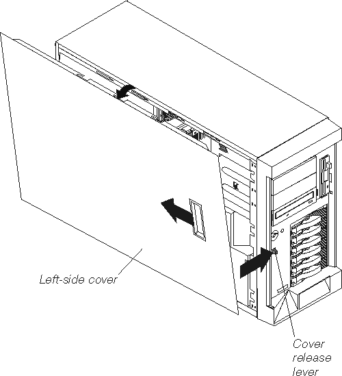
To remove the left-side cover of the Model 100:
- Review the information in Preparing to install a memory module.
- Switch off the appliance and all attached devices and disconnect all
external cables and power cords.
- Slide the cover-release lever on the front of the appliance to release the
cover; then, slide the cover toward the rear of the appliance about 25 mm
(1 in.). Move the top edge of the cover out from the
appliance; then, lift the cover off the appliance. Set the cover
aside.
Attention: For proper cooling and airflow, replace the cover
before switching on the appliance. Operating the appliance for extended
periods of time (over 30 minutes) with the cover removed might damage
appliance components.
Figure 6. Removing the cover of the Model 200
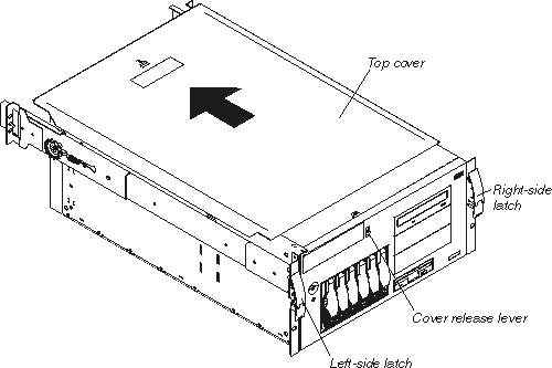
To remove the appliance top cover:
- Review the information in Preparing to install a memory module.
- Switch OFF the appliance and all attached devices and disconnect all
external cables and power cords.
- Release the left and right side latches and pull the appliance out of the
rack enclosure until both slide rails lock.
- Note:
- When the appliance is in the locked position, you can reach the cables on the
back of the appliance.
- Move the cover-release lever down while sliding the top cover toward the
rear of the appliance about 25 mm (1 in.). Lift the cover off
the appliance and set the cover aside.
Attention: For proper cooling and airflow, replace the cover
before switching on the appliance. Operating the appliance for extended
periods of time (over 30 minutes) with the cover removed might damage
appliance components.
Read these notes before adding the memory module.
- Note:
- The Model 100 supports additional 256-MB, 512-MB, and 1-GB DIMMs. The
Model 200 supports additional 512-MB DIMMs. Both models support a
maximum of 2-GB of memory.
To install a memory module (DIMM):
Attention: When you handle electrostatic discharge-sensitive
devices (ESDs), take precautions to avoid damage from static
electricity. For details on handling these devices, refer to Handling electrostatic discharge-sensitive devices.
- Review the safety precautions listed in Statement 1 and Statement 5 in Translated safety notices.
- Review the documentation that comes with your option.
- Switch off the appliance and peripheral devices and disconnect all
external cables and power cords.
- Touch the static-protective package containing the DIMM to any unpainted
metal surface on the appliance. Then, remove the DIMM from the
package.
- Note:
- To avoid breaking the retaining clips or damaging the DIMM connectors, handle
the clips gently.
- Install the DIMM:
- Turn the DIMM so that the pins align correctly with the connector.
- Insert the DIMM into the connector by pressing on one edge of the DIMM and
then on the other edge of the DIMM. Be sure to press straight into the
connector. Be sure that the retaining clips snap into the closed
positions.
- Make sure the retaining clips are in the closed position. If a gap
exists between the DIMM and the retaining clips, the DIMM has not been
properly installed. In this case, open the retaining clips and remove
the DIMM; then, reinsert the DIMM.
Figure 7. Installing a DIMM
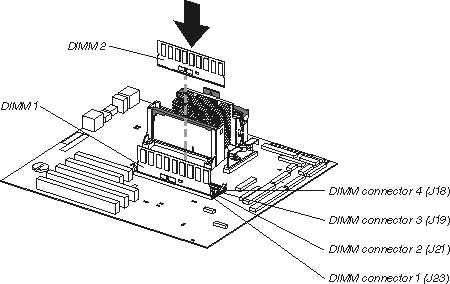
- Install additional DIMMs in the order specified in the documentation that
comes with your option. (See Figure 7 for memory connector locations.)
- Continue with Replacing the cover.
Figure 8. Replacing the Model 100 cover
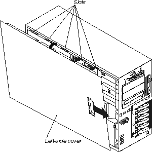
To replace the appliance left-side cover:
- Align the cover with the left side of the appliance, about 25 mm
(1 in.) from the front of the appliance; place the
bottom of the cover on the bottom rail of the chassis.
- Insert the tabs at the top of the cover into the slots at the top of the
appliance.
- Hold the cover against the appliance and slide the cover toward the front
of the appliance until the cover clicks into place.
- Connect a keyboard and monitor to the appliance.
- Switch on the appliance.
- The system displays a message indicating that a configuration error
occurred. Follow the onscreen prompts to review and save the new memory
configuration. After you save changes and exit the
Configuration/Setup Utility program, the appliance will
restart.
- Disconnect the keyboard and monitor.
Figure 9. Replacing the Model 200 cover
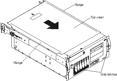
To replace the appliance top cover:
- Align the top cover with the top of the appliance, about 25 mm
(1 in.) from the front of the appliance; the flanges on
the left and right sides of the cover should be on the outside of the
appliance chassis.
- Hold the cover against the appliance and slide the cover toward the front
of the appliance until the cover clicks into place.
- Connect a keyboard and monitor to the appliance.
- Switch on the appliance.
- The system displays a message indicating that a configuration error
occurred. Follow the onscreen prompts to review and save the new memory
configuration. After you save changes and exit the
Configuration/Setup Utility program, the appliance will
restart.
- Disconnect the keyboard and monitor.
Refer to the instructions that come with your Tower-to-Rack Kit for
information on converting a tower to a rack.
[ Top of Page | Previous Page | Next Page | Table of Contents | Index ]