The TMS7000 - Texas Instruments 8-bits Microprocessor/Microcontroller line
Texas instruments produced an interesting 8-bit processor line, deployable both as
microprocessor and microcontroller, much like the Motorola MC6801. It has a very flexible
architecture, allowing the customer to specify custom instructions. The microcode for these
instructions were added as a slice in the silicon die.
Arriving a bit too late to be part of the 8-bit (home-)computer bubble in the '80s, it was used in one
TI computer (the CC-40)
and one calculator (the TI-74). Its main
platform was embedded in modems and similar DSP devices.
There are two development environments for the TMS7000 family:
| EVM |
 |
TMS7000 Family Low Cost Development System
- Single-Chip Mode Emulation Only
- On-Board Assembler/Line Text Editor
- On-Board Hardware/Software Debugger
- Multiple Breakpoints
|
XDS |
 |
XDS — extended development system
- Full TMS7000 Family Development System
- Host Independent/RS-232-C Interface
- Full Speed 8 MHz In-Circuit Emulation
- Extensive Breakpoint and Trace Functions
- Detailed Timing Analysis
- 2K-Byte Trace Samples
- Breakpoint Sequencing Ability
- Command/Default Storage
- Removable Target Connector
- External Probe for Breakpoint/Trace Qualifiers
- On-Board Assembler and Reverse Assembler
- Multiprocessing Capabilities
|
The Evaluation Module
The TMS7000 Evaluation Module exists in several versions, the NMOS TMS7000 and the CMOS TMS7000C.
On the Evaluation Module, the TMS70C02 I.C. is operated in microprocessor mode, using an NSC810A as
port extender for the ICE function. Three 8-kByte EPROMs contain the DEBUG MONITOR and five 8-kByte memory sockets
could contain EPROM or RAM. The board also has a program facility for PROM-based processors and EPROMs.
| Overview |
 |
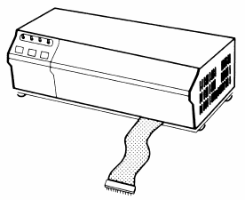
An overview of the Evaluation Module. It contains a 40-pin pod cable (far left) to the processor socket on the
target board, the TMS70C02 processor next to it and the NS810A port extender below it. At the bottom of the picture
are five RAMs, 8 kByte each and three EPROMs containing the DEBUG MONITOR. On the top half are two ZIF-sockets for
EPROM and programmable processors. A programming voltage can be supplied from the two power connectors
at the top. Normal operating voltages are +5V/1A for most components and +/-12V/0.1A for the RS-232c ports. Both
ports share the single serial port of the processor. Port one is intended for the terminal, port two for the 'host'.
Three mini-jacks allow connection of a cassette recorder. Just below that is the cassette motor relay.
The actual size of the board is 305x205mm.
|
| Connection |
 |
The module port 1 is a proper DCE device, so works with a direct connection to a DTE (2-Rx, 3-Tx, 7-GND on port J1).
Press the Enter key on the terminal to have the BAUD rate determined (9600 BAUD, 8 bits, no parity, one stop bit works ok).
This is the startup message:
	TMS7000 DEBUG MONITOR  REV 1.4
	HELP:HE /H $HE
	MOD:MM MR MP  A/MA B/MB MS-P/PC,SR,SP
	DISP:DM/DH DS IO
	STATE:C/CP D/DP  EI DI  DV
	SAVE:SM ST DS
	LOAD:LM LT LS
	MOVE:MV
	FIND:FB
	FILL:FM NP  FR
	RESET:RT T0
	BRKPT:B1 B2 C1 C2 CB DB  BT CT DT
	TRACE:TO TF IT PT IS  TC TR
	DEBUG:SS TS FS CS  CY  GO EX ET EF  RU
	TED:XE  L1 L2 LL LA LN
	ASSM:XA XL XP  AT  XR
	EPROM:PE VE CE RE  BC  12 21 25
	MATH:HC DC AR
PORTS:BR DR MO |
| |
![]() |
|
Last update: 2024-03-21
fjkraan@electrickery.nl
